
Twist system fiber filter

A fiber filter and fiber bundle technology, which is applied in the field of liquid-solid separation devices, can solve the problems of uneven filtration pores, unstable effluent quality, slow filtration speed, etc. easy effect

Inactive Publication Date: 2008-08-27
郭建良
View PDF2 Cites 13 Cited by
  • Summary
  • Abstract
  • Description
  • Claims
  • Application Information

AI Technical Summary

Problems solved by technology

[0004] The patent of the present invention provides a twisted fiber filter, which solves the technical problem of unstable effluent water quality, and solves the technical problems of uneven filtration pores, slow filtration speed and poor effect of existing fiber bundle filters

Method used


Image

  • Twist system fiber filter
  • Twist system fiber filter
  • Twist system fiber filter

Examples


Embodiment 1

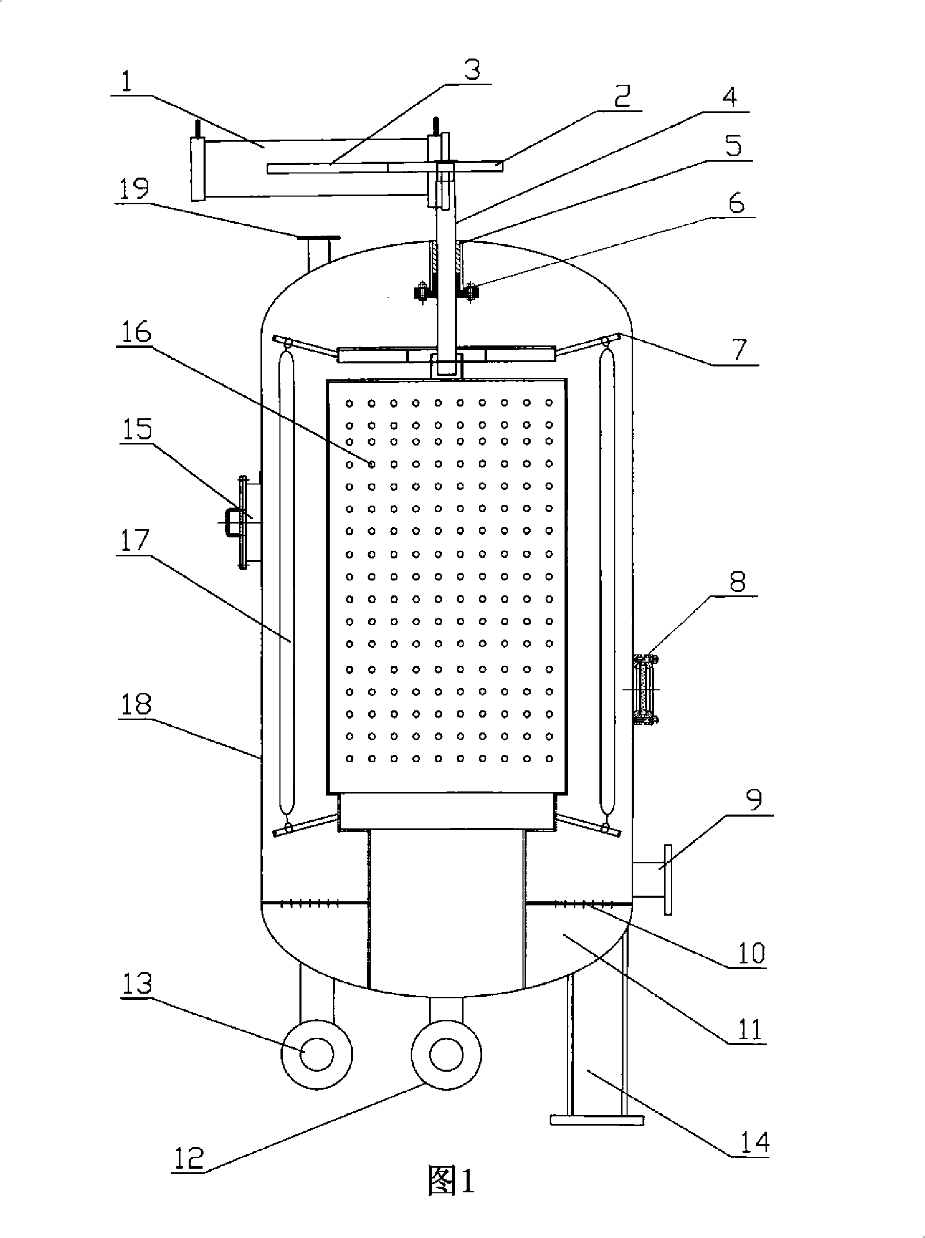
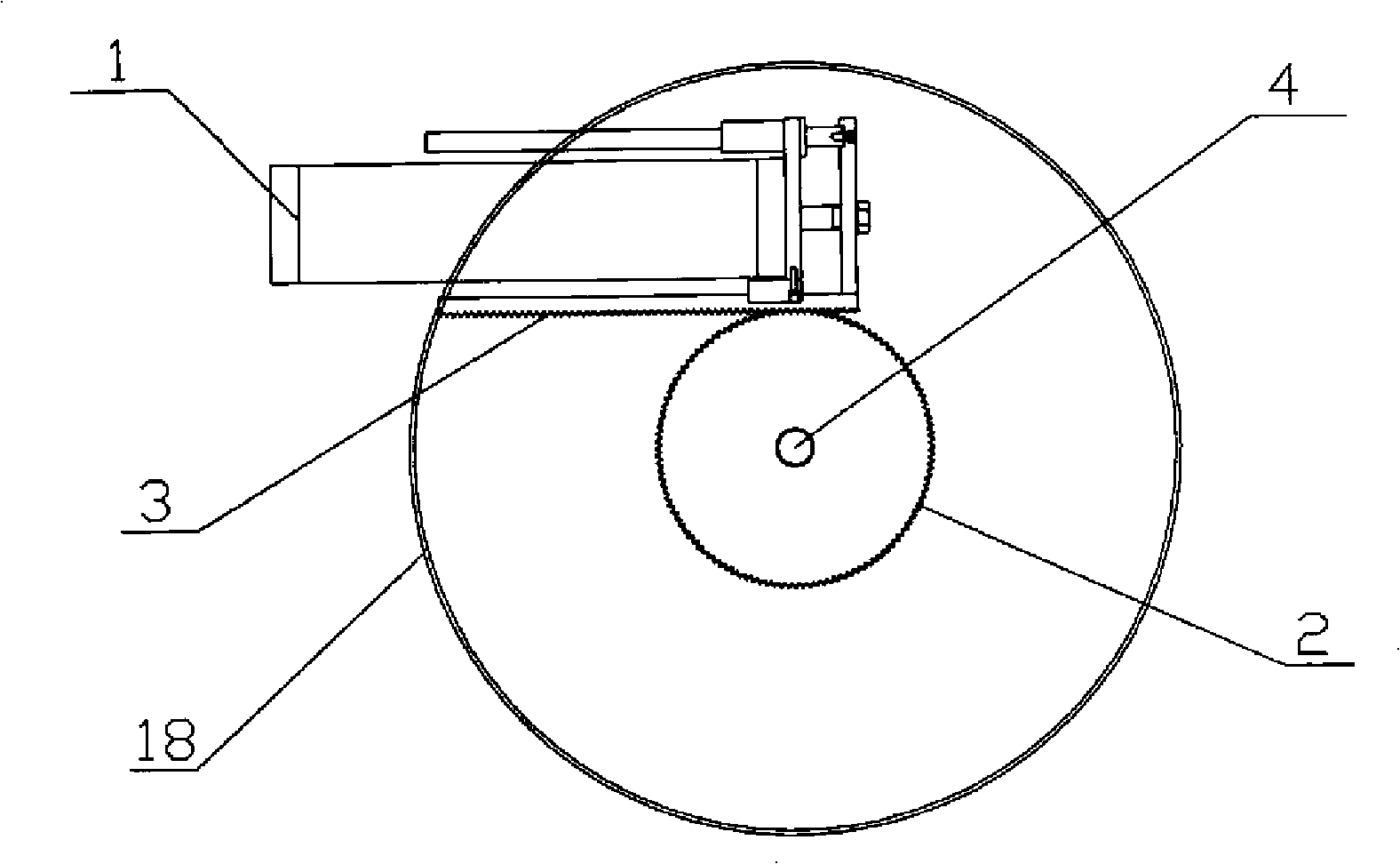
[0026] Embodiment 1 see Figure 1- image 3 , this single element twisted fiber filter includes a housing 18, fiber bundles inside the housing and a fiber bundle support body, the housing is provided with an inlet pipe 9 and an outlet pipe 12, and it is characterized in that: the housing interior is equipped with at least A porous filter cartridge 16, the bottom of each porous filter cartridge is connected to the transmission shaft 4, the transmission shaft 4 passes through the outside of the housing, and is connected to the torsion drive device 1 through the transmission mechanism; the outlet end of the porous filter cartridge passes through the air distribution plate 10 communicates with the water outlet pipe 12, air holes are distributed on the air distribution plate 10, and the air distribution plate is divided into an air distribution chamber 11 at the head of the shell. There is a backwash drain pipe 19; the above-mentioned transmission shaft and the outlet end of the por...

Embodiment 2

[0033] Embodiment 2 is a twisted fiber filter with multiple filter elements, see Fig. 4 Figure 5 , the difference from Embodiment 1 is that four or more porous filter cartridges 16 are arranged inside the housing, and one or more driving devices 1 are arranged outside the housing, and the driving devices drive four or more filter cartridges by rotating the rack respectively. Gear 2 rotates, and gear 2 is connected with an end of transmission shaft 4 respectively again, and the other end of transmission shaft 4 is connected with top hanging screw rod 7 again.

[0034] The straight pipes at the bottom of four or more porous filter cartridges 16 are all connected to the outlet pipe 12 outside the housing, and the outer sides 21 of the straight pipes are respectively provided with air distribution discs 10, and the backwash air inlet pipe 13 at the bottom of the housing is divided into four or more, communicating with four or more air distribution chambers 11 respectively.

[00...


PUM


Abstract

A torsion type fiber filter includes a shell body, a fiber beam in the shell body and fiber beam supporting bodies, a water inlet pipe and a water outlet pipe are arranged on the shell body, the interior of the shell body is provided with at least one porous filter cylinder, one end part of each porous filter cylinder is connected with a transmission shaft, the transmission shaft penetrates out of the shell body and is connected with a torsion drive device by a transmission mechanism. The outside of the transmission shaft and the outlet end of the porous filter cylinder are respectively surrounded by a circle of fiber beam supporting body, the fiber beam supporting bodies include wire hanging rods which are evenly arranged in a horizontal radial pattern, and the fiber wires are evenly fastened between the two circles of fiber beam supporting bodies, so as to form a fiber beam filter layer which surrounds the outer wall of the porous filter cylinder. The filtration area of the torsion type fiber filter is the outer surface area of the porous filter cylinder, so as to eliminate the limitation of the diameter on the filtration area, greatly improve the filtration speed and reduce the area coverage.

Description

technical field [0001] The invention relates to a liquid-solid separation device, in particular to a fiber filter. Background technique [0002] At present, known fiber filters include housings, fiber bundles, fiber bundle supports, water inlet pipes, and water outlet pipes. They are filter devices using fiber bundles as filter materials. The compactness of fiber bundles directly affects the quality and accuracy of filtration. The Chinese patent "Filtration Method and Equipment of Media" (Patent No. 87100467) discloses a fiber filtration method and equipment, in which capsules are set in a filter layer made of fiber bundles to adjust the density of the filter layer. Later, based on this patent, several fiber filter devices using capsule compression filter layers were disclosed. Its main disadvantages are: the filter layer is compressed unevenly, resulting in unstable effluent quality; the capsule used for compression is easily broken, resulting in equipment failure. [000...

Claims


Application Information

Patent Timeline
Patent Type & Authority Applications(China)
IPC IPC(8): B01D29/33
Inventor 郭建良
Owner 郭建良
Learn More