Electric cooking appliance

A technology of electric cooking utensils and connecting seats, which is applied in the direction of electric heating devices, electrical components, household appliances, etc., can solve the problems of breaking, troublesome cleaning of the upper cover, poor contact between connecting wires and circuits, etc., and achieves a simple and reasonable structure and a high degree of safety. Effect

Active Publication Date: 2008-08-27
GUANGDONG GALANZ GRP CO LTD
View PDF0 Cites 3 Cited by
  • Summary
  • Abstract
  • Description
  • Claims
  • Application Information

AI Technical Summary

Problems solved by technology

Its shortcoming is that this structure can only be adapted to the electric rice cooker that the pot body and the pot cover are hinged, but not for the electric cooker that needs to separate the pot cover from the pot body, and because the setting of the connecting wire must pass through the hinge mechanism, every time the pot cover When it is opened and closed for the first time, it will be involved, which will easily lead to poor contact or breakage between the connecting wire and the circuit, making the pressure control protection fail
The pressure valve has a spring between its core and the valve body, which causes the valve core to move to different positions, and the pressure it receives varies with the compressed length of the spring, which makes the pressure control accuracy of overpressure protection inaccurate.
The electric rice cooker with this structure also cannot separate the upper cover to cook rice or do other cooking, so it brings a lot of inconvenience, especially the cleaning of the upper cover is very troublesome

Method used


Image

  • Electric cooking appliance
  • Electric cooking appliance
  • Electric cooking appliance

Examples


Embodiment Construction

[0024] The present invention will be further described below in conjunction with the accompanying drawings and embodiments.

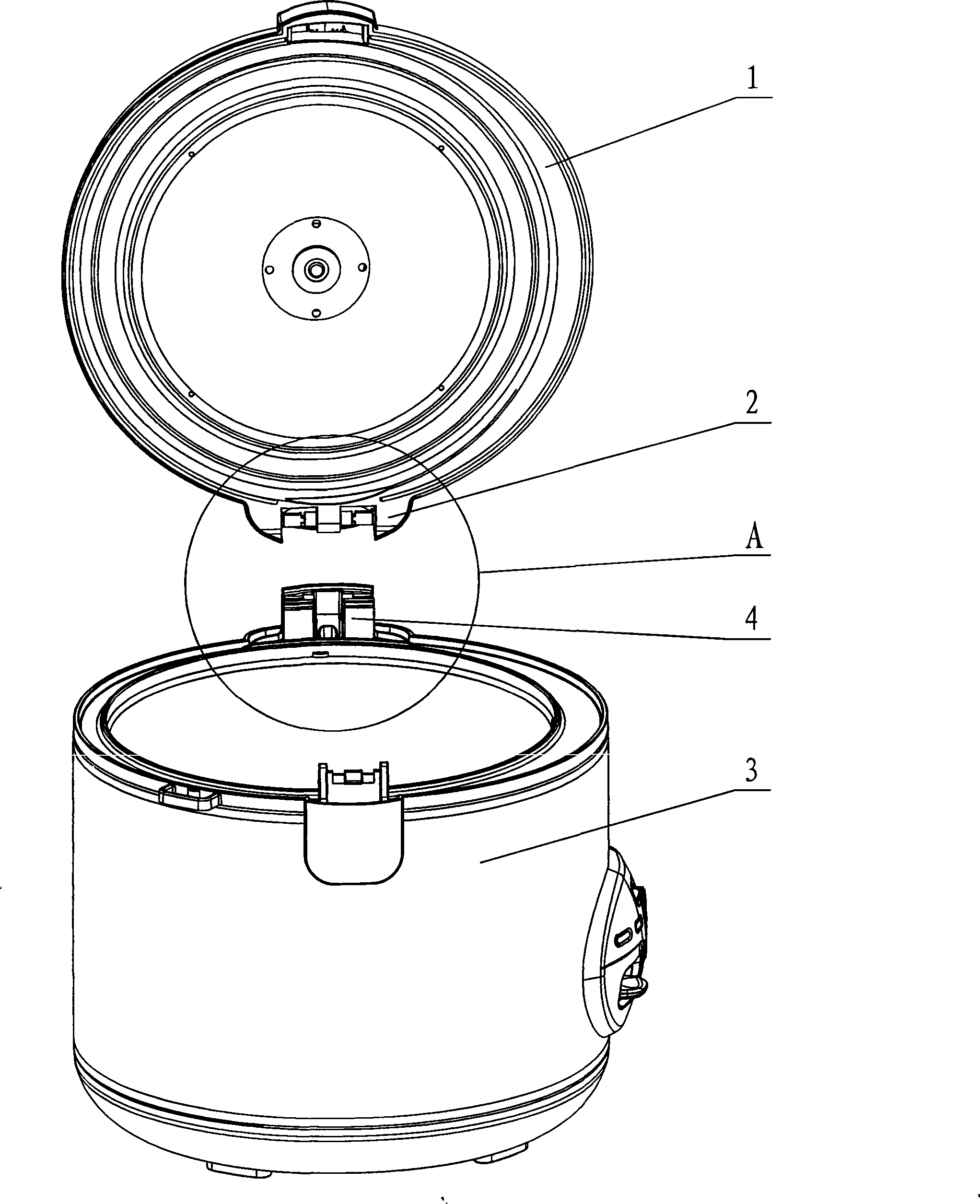
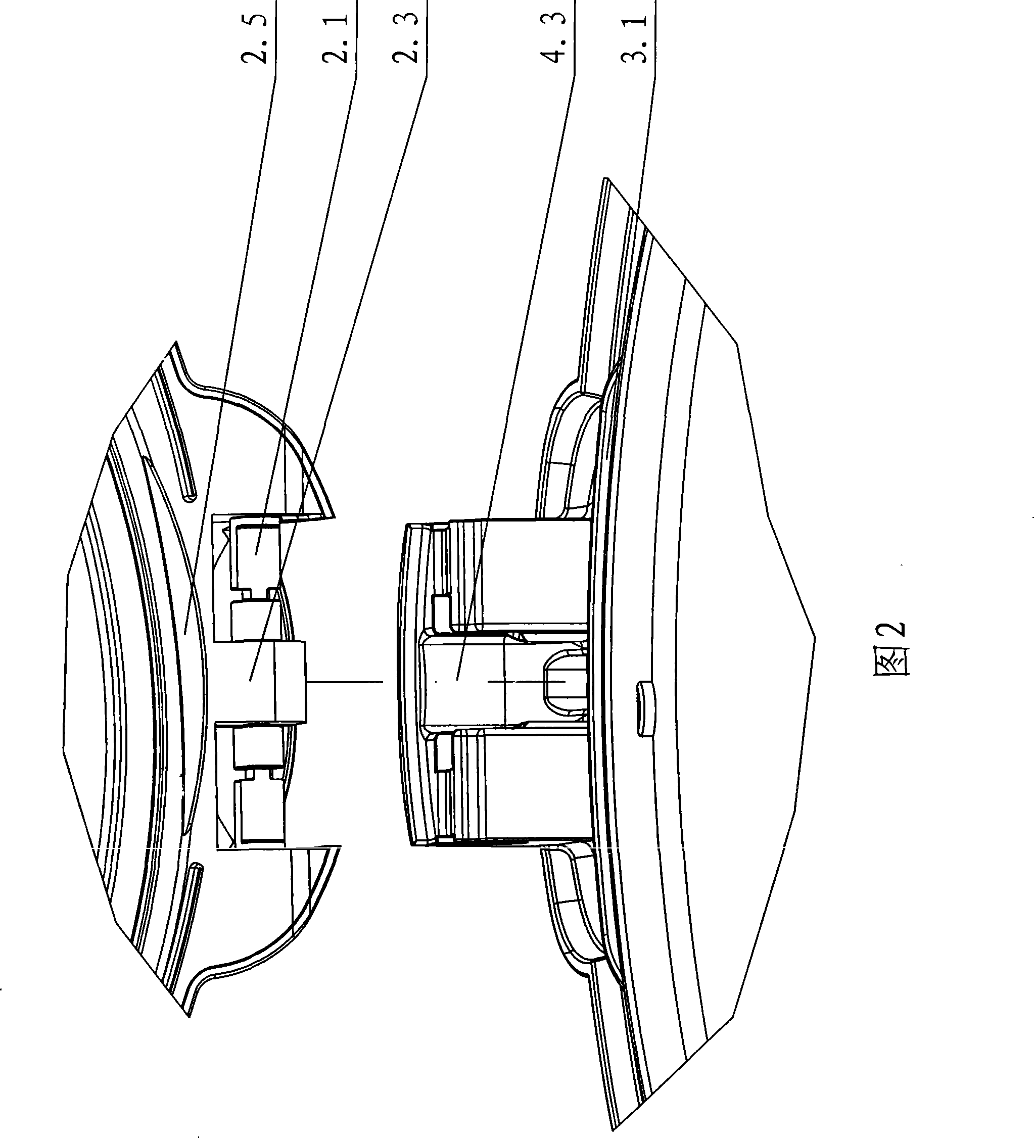
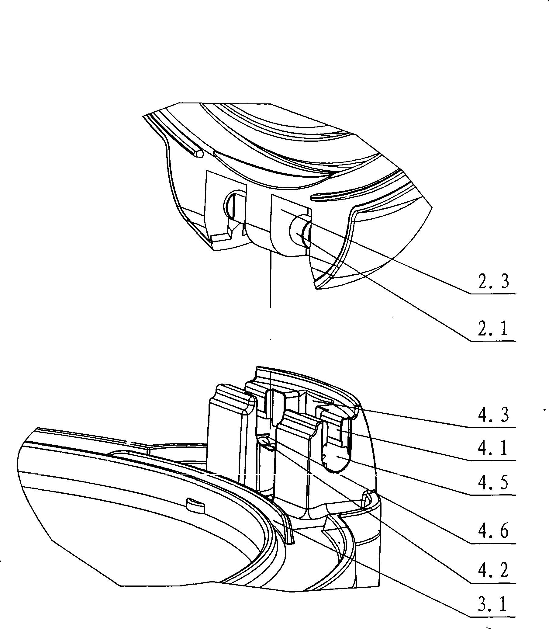
[0025] see figure 1 - Fig. 6, the electric cooker includes an upper cover 1 pivotally arranged on the pot body 3, the upper cover is provided with an upper connecting seat 2, the pot body is provided with a lower connecting seat 4, and the upper connecting seat 2 is inserted into the lower connecting seat 4 There are grooves on the upper and upper connecting seats, and a boss 2.3 is arranged in the center of the groove. The two conductive shafts 2.1 and the upper connecting terminals 2.2 for the live wire and the neutral wire are respectively arranged on the left and right sides of the boss, and the lower connecting seat 4 corresponds to the boss. The table is provided with a turn slot 4.3, and two assembly grooves 4.5 are respectively arranged on both sides of the turn slot. A conductive rotating shaft 2.1 with an upper connection terminal 2.2 is arra...


PUM


Abstract

The invention relates to an electric cooker, comprising an upper cover pivotedly arranged on a cooker body, wherein an upper connecting seat is arranged on the upper cover, a lower connecting seat is arranged on the cooker body, two conductive rotating shafts with upper connecting terminals are arranged inside the upper connecting seat, an assembly groove is formed inside the lower connecting seat, and a lower connecting terminal is arranged in the assembly groove. The conductive rotating shaft is provided with a flat segment with triangular, rectangular, waist drum-shaped, lozenged, ellipsoidal, long round or spindle-shaped cross section, an opening groove is arranged above the assembly groove and communicates with the assembly groove, and the width of the opening groove is less than that of the assembly groove. The upper connecting seat is plugged into the lower connecting seat, a groove is arranged on the upper connecting seat and provided at the center thereof with a boss, the two conductive rotating shafts respectively used for a live line and a zero line and the upper connecting terminals thereof are respectively arranged at the left and the right sides of the boss, and the lower connecting seat is provided with a rotary groove corresponding to the boss. The inventive electric cooker has the advantages of simple and reasonable structure and high safety.

Description

technical field [0001] The invention relates to an electric cooking utensil, which includes an electric rice cooker, an electric slow cooker, an electric purple sand pot, an electric ceramic pot, an electric steamer, an electric cooking pot, an electric chafing dish, an electric frying pan, an electric heating pot, an electric Shih Tzu pot, an electric Wok, electric pressure cooker or electric bread machine. Background technique [0002] Existing electric rice cooker comprises pot body and pot lid, is provided with electric heater and the electric controller that controls electric heater work in the pot body, is provided with the pressure valve of induction pot internal pressure or the temperature sensor of induction pot on the pot cover. Temperature controller, when the pressure or the temperature controller senses that the pressure in the pot reaches the set temperature, it will touch the button switch set on the pot cover to make the button switch act, cut off the electri...

Claims


Application Information

Patent Timeline
IPC IPC(8): A47J27/086A47J27/08A47J27/00A47J36/06H05B1/02
Inventor 李基成
Owner GUANGDONG GALANZ GRP CO LTD
Why Eureka
Try Eureka