Front window shield for vehicle
A vehicle and front window technology, which is applied to the field of vehicle front windows, can solve the problems that the burden of assembling operators cannot be reduced, the number of components is large, and the manufacturing cost is expensive, and the effect of a simple and inexpensive structure is achieved.
- Summary
- Abstract
- Description
- Claims
- Application Information
AI Technical Summary
Problems solved by technology
Method used
Image

Examples
Embodiment approach 1
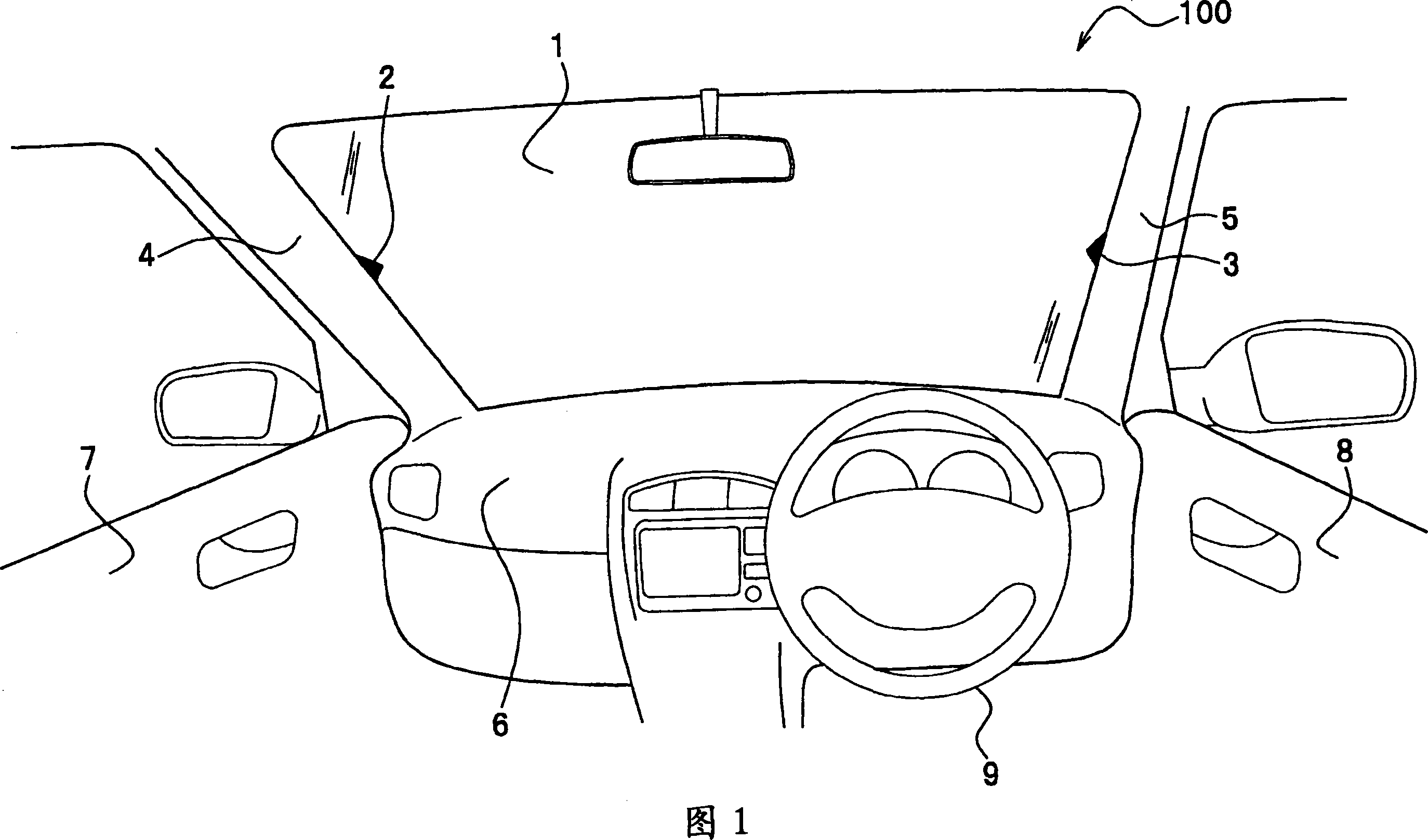
[0056] First, referring to the schematic diagram shown in FIG. 1, a vehicle front window according to Embodiment 1 will be described. That is, the situation when the vehicle is in contact with a horizontal road will be described here.
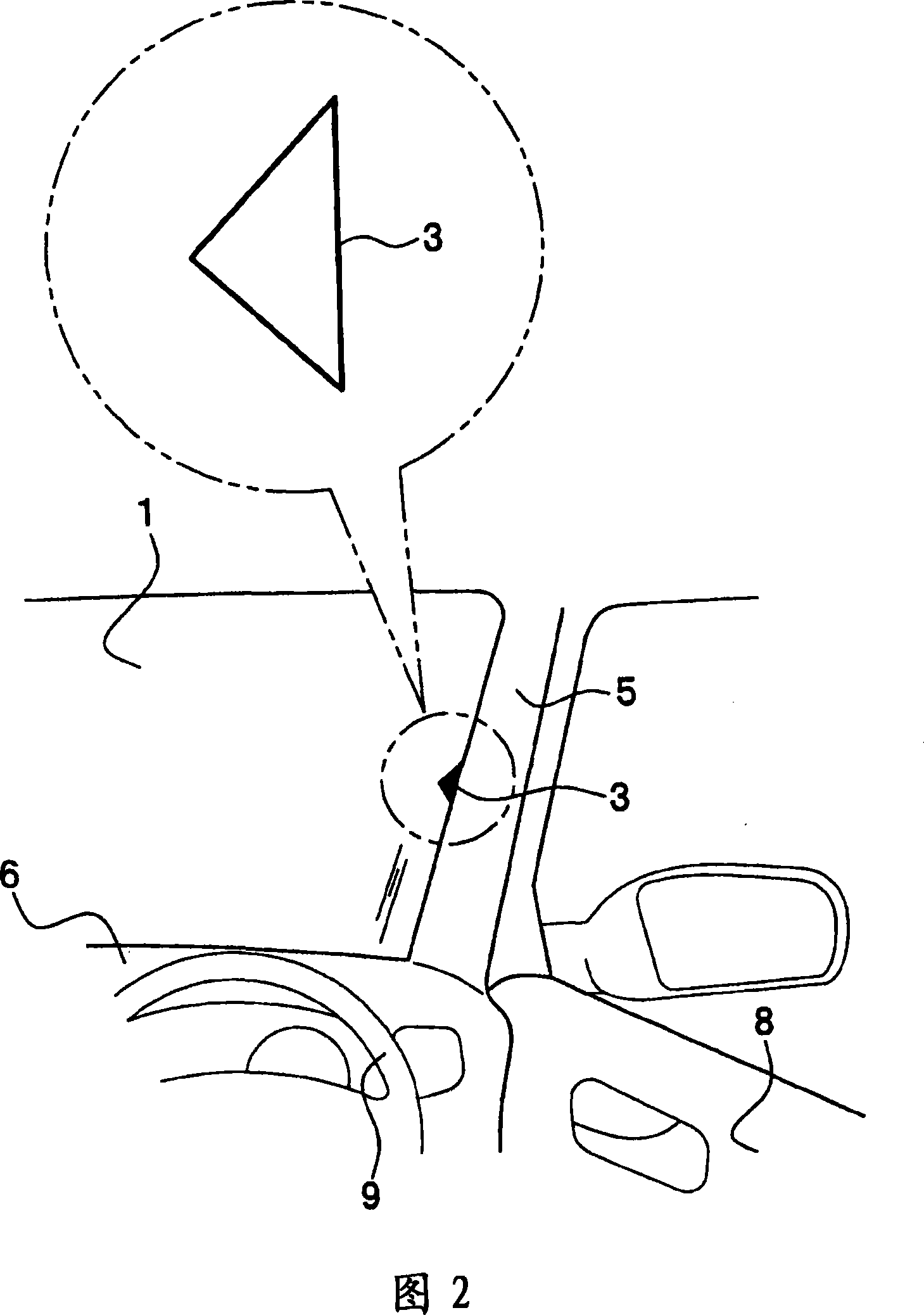
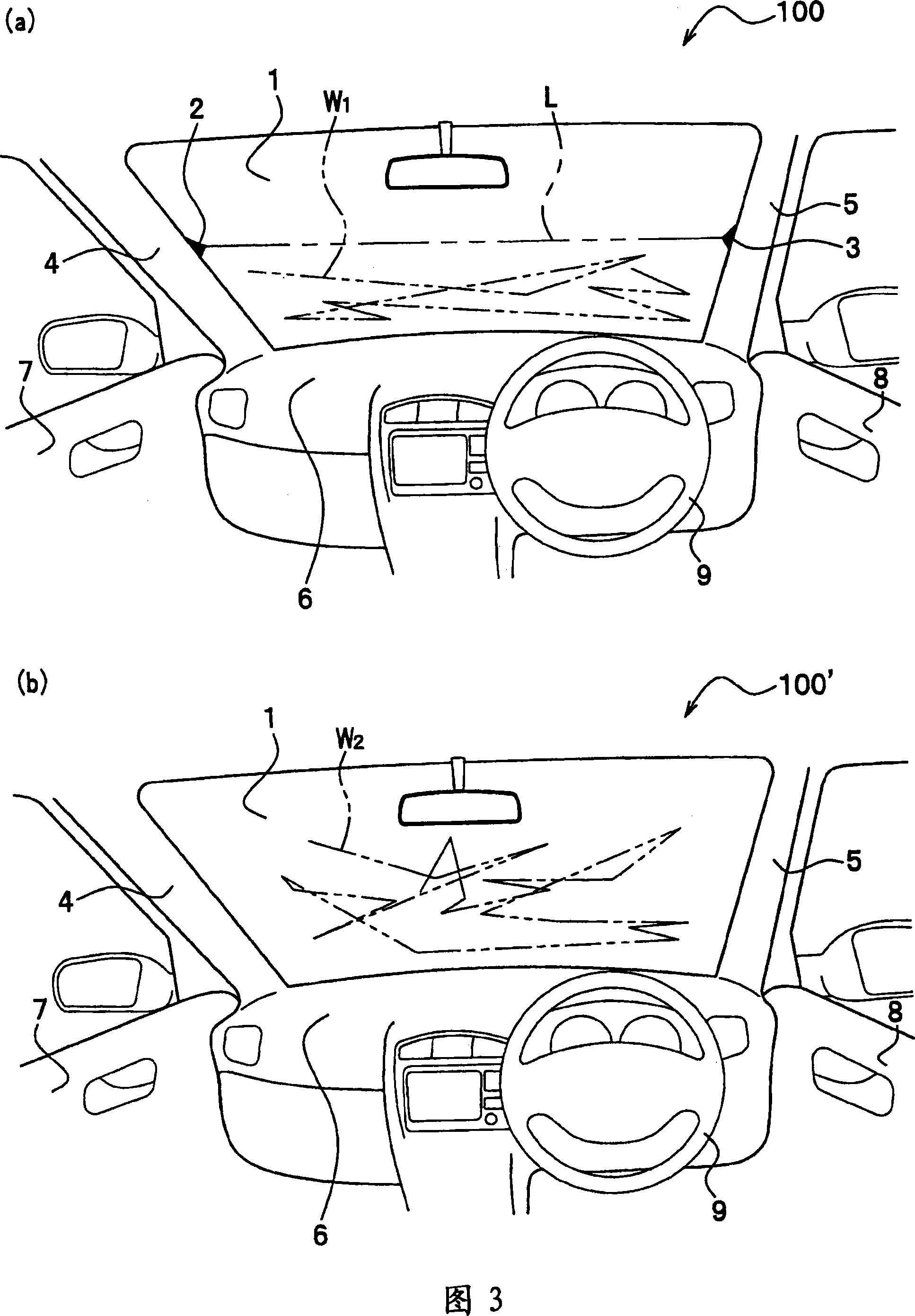
[0057] As shown in Fig. 1, in this vehicle 100, a pair of marks 2 and 3 showing a substantially horizontal direction are provided on a vehicle front window (hereinafter referred to as "front window") 1 for a vehicle. The marks 2 and 3 are formed at the same height positions on the left and right sides of the front window 1. In this way, the driver can perceive a virtual straight line connecting the pair of marks 2 and 3.
[0058] The marks 2 and 3 are formed of so-called black ceramic prints (hereinafter referred to as "black porcelain"). Therefore, when black porcelain is formed on the glass edge of the front window 1, etc., a part of it may be a pair of isosceles triangle shapes, and the marks 2 and 3 may be formed on the front window 1. In addit...
Embodiment approach 2
[0089] Next, referring to the schematic diagram shown in FIG. 8, the front window of Embodiment 2 will be described. In addition, in FIG. 8, reference numerals 1, 4, 5, 6, 7, 8, and 9 are the same as those shown in FIG. In this vehicle 300, areas 1a and 1b having lower transmittance than the high transmittance area of the front window 1 are formed in the center of the upper and lower portions of the front window 1. Therefore, the high transmittance regions other than the low transmittance regions 1a and 1b are formed in a substantially H-shape.
[0090] Furthermore, the difference in transmittance between the high area and the low area may be any different ratio as long as the two can be distinguished. In addition, the regions 1a and 1b may be formed such that the transmittance changes when viewed from the driver's seat side (here, the right side). The regions 1a and 1b are formed by sandblasting the front window 1, but they are not limited to this as long as they have a structu...
Embodiment approach 3
[0098] Next, referring to the schematic diagram shown in FIG. 9, a vehicle front window according to Embodiment 3 will be described. In addition, in FIG. 9, reference numerals 1, 4, 5, 6, 7, 8, and 9 are the same as those shown in FIG. In this vehicle 400, when viewed from the driver’s seat, the lower end edge B of the front window 1 has a substantially horizontal linear shape, and the left end of the lower end edge B and the horizontal waistline A intersect on the left front pillar 4 , The right end of the lower edge B and the horizontal waistline C cross on the right front pillar 5. That is, the lower end edge B and the waistline A and C have the same height.
[0099] The lower end edge B is formed in a substantially horizontal curved shape, and is composed of black porcelain (edge auxiliary body) 1c formed in a linear shape that is substantially horizontal when viewed from the driver's seat. Since the front window 1 is formed in the shape of a curved surface protruding forwar...
PUM
 Abstract
Description
Claims
Application Information
 - Generate Ideas
- Intellectual Property
- Life Sciences
- Materials
- Tech Scout
- Unparalleled Data Quality
- Higher Quality Content
- 60% Fewer Hallucinations
Browse by: Latest US Patents, China's latest patents, Technical Efficacy Thesaurus, Application Domain, Technology Topic, Popular Technical Reports.
© 2025 PatSnap. All rights reserved.Legal|Privacy policy|Modern Slavery Act Transparency Statement|Sitemap|About US| Contact US: help@patsnap.com