
Power supply system for slide door

A technology of power supply device and sliding door, which is applied in the installation of cables, the arrangement of cables between relatively moving parts, and doors, etc., which can solve the problems that the bellows cannot be bent greatly, and is easily damaged and damaged, so as to improve the soundness , to avoid the effect of sagging

Active Publication Date: 2008-08-13
FURUKAWA ELECTRIC CO LTD
View PDF4 Cites 15 Cited by
  • Summary
  • Abstract
  • Description
  • Claims
  • Application Information

AI Technical Summary

Problems solved by technology

[0007] However, since the power supply device for sliding doors described in Patent Document 1 has a structure in which the wires are pulled out from the bare wires of the winding assembly, the wires rub against other components (sliding rails, etc.) and are easily damaged.
In addition, the winding unit needs to draw out or wind up the electric wire which is about the same length as the opening and closing stroke of the sliding door, so there is also a problem of increasing the size of the device.
[0008] In addition, in the power supply device for a sliding door described in Patent Document 2, although the wire harness is accommodated in a corrugated tube to reduce the possibility of damage, the corrugated tube in which the harness is included needs to be long enough to absorb the opening and closing stroke of the sliding door.
In particular, since the round wire is used as the harness, the corrugated tube cannot be bent to a large extent, and in order to distribute the cable with a certain bending allowance, not only a large space is required, but also the corrugated tube may be loosened from other parts. Contact, resulting in abnormal noise or damage

Method used

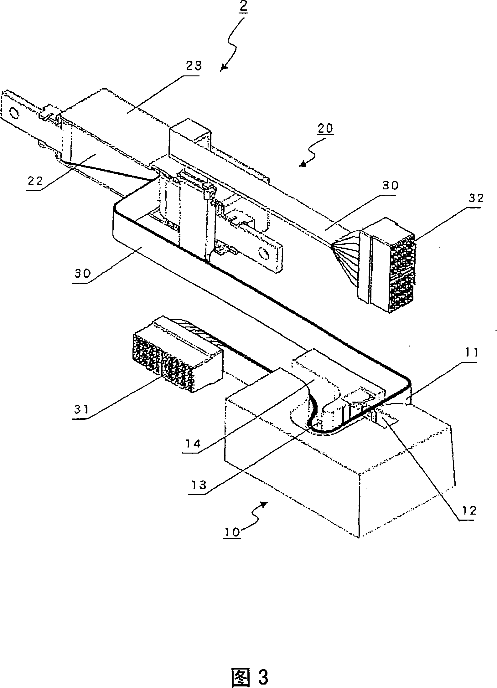

Image

  • Power supply system for slide door
  • Power supply system for slide door
  • Power supply system for slide door

Examples


Embodiment Construction

[0071] The configuration of the power supply device for a sliding door in a preferred embodiment of the present embodiment will be described in detail with reference to the drawings. In addition, components having the same function are denoted by the same reference numerals for simplification of illustration and description.

[0072] FIG. 1 is a perspective view showing a schematic configuration of a power supply device for a sliding door according to an embodiment of the present invention. The power supply device 1 for a sliding door according to this embodiment has a vehicle body side fixing unit 10 fixed at a predetermined position of the vehicle body and a door side fixing unit 20 fixed at a predetermined position of the sliding door. Flat cables 30 are distributed between them.

[0073] In the power supply device 1 for a sliding door according to this embodiment, the overlapping portion between the vehicle body side fixing unit 10 and the door side fixing unit 20 uses a ...


PUM


Abstract

The present invention provides a power supply system for a slide door capable of reducing a possibility that a wire harness for feeding power to the slide door is damaged due to its contact on a vehicle body and the slide door, enabling a reduction in the number of parts, and enabling the easy reduction in size. The power supply system (1) comprises a vehicle body side fixed unit (10) fixed to a vehicle body at a predetermined position and a door side fixed unit (20) fixed to the slide door at a predetermined position. A flat cable (30) is disposed between the vehicle body side fixed unit (10) and the door side fixed unit (20). Predetermined lock mechanisms are installed in the vehicle body side fixed unit (10) and the door side fixed unit (20), and a permanent bending in a specified direction is provided to the flat cable (30) to reduce a possibility that the flat cable is brought into contact with the vehicle body and the slide door.

Description

technical field [0001] The invention relates to a power supply device for a sliding door, which is used for continuous power supply and signal transmission from the vehicle body side to equipment inside the sliding door. Background technique [0002] A power window motor, a switch, a speaker, and the like are assembled in a sliding door used on a van or a truck. In order to supply power to these devices from the vehicle body side, it is necessary to route electric wires (harnesses) from the vehicle body side to the sliding door side so that the electric wires can follow the opening and closing of the sliding door. As the wire harness, a highly bendable round wire is currently used. [0003] At present, as such a power supply device for a sliding door, there is known a method in which an electric wire winding unit is provided on the vehicle body side, and the excess length of the electric wire accompanying the opening and closing of the sliding door is absorbed by winding th...

Claims


Application Information

Patent Timeline
IPC IPC(8): B60R16/02B60J5/06H02G3/04H02G11/00
CPCH02G3/0468B60R16/0207H02G11/006B60J5/06B60Y2200/11
Inventor 榎本宪嗣牛山政利向井康彦
Owner FURUKAWA ELECTRIC CO LTD
Learn More