Engine decorative cover and cylinder cover assembly structure
An assembly structure and decorative cover technology, which is applied in the direction of engine components, engine frame, machine/engine, etc., can solve the problems of resonance between decorative cover and engine, inconvenient disassembly and assembly of engine decorative cover, etc.
- Summary
- Abstract
- Description
- Claims
- Application Information
AI Technical Summary
Problems solved by technology
Method used
Image
Examples
Embodiment Construction
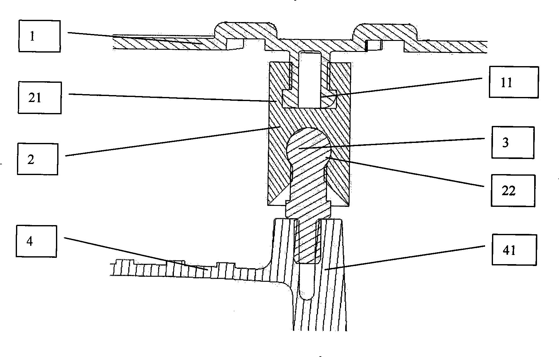
[0010] See figure 1 , The engine decorative cover and cylinder cover assembly structure includes engine decorative cover 1, rubber sleeve 2, ball head bolts 3 and cylinder cover 4. The inner side of decorative cover 1 and cylinder cover mounting boss 41 are arranged perpendicular to the surface of the decorative cover. The upper end of the rubber sleeve 2 is provided with a T-shaped groove 21 for clamping with the T-shaped boss 11, and the lower end of the rubber sleeve 2 is provided with a ball socket 22 for clamping with the ball bolt 3. During installation, the T-shaped boss 11 of the decorative cover is clamped with the T-shaped slot 21 of the rubber sleeve, and the T-shaped structure of the boss is used to clamp the rubber sleeve, so that the decorative cover 1 and the rubber sleeve 2 become a relatively fixed body. To ensure that the rubber sleeve is not separated from the decorative cover when the user disassembles the decorative cover. The ball head bolt 3 is pre-assembled...
PUM
 Abstract
Description
Claims
Application Information
 - R&D
- Intellectual Property
- Life Sciences
- Materials
- Tech Scout
- Unparalleled Data Quality
- Higher Quality Content
- 60% Fewer Hallucinations
Browse by: Latest US Patents, China's latest patents, Technical Efficacy Thesaurus, Application Domain, Technology Topic, Popular Technical Reports.
© 2025 PatSnap. All rights reserved.Legal|Privacy policy|Modern Slavery Act Transparency Statement|Sitemap|About US| Contact US: help@patsnap.com

