Water fin removing tool

A water fin and horizontal plane technology, applied in water conservancy projects, marine engineering, coastline protection, etc., can solve the problems of increasing the pulsating pressure of the side wall of the spillway, increasing the height of the side wall of the spillway, and disorder of the flow state of the spillway, so as to eliminate the water fins. Phenomenon, simple structure, the effect of improving water flow

Inactive Publication Date: 2008-08-06
SICHUAN UNIV
View PDF0 Cites 4 Cited by
  • Summary
  • Abstract
  • Description
  • Claims
  • Application Information

AI Technical Summary

Problems solved by technology

[0002] In the spillway layout of water conservancy and hydropower projects, due to the large overflow width of many spillways, gate piers are required in the middle. In order to meet the structural stability requirements of gate slots and gate piers, the width of spillway gate piers is often greater than 3m, and the spillway gate hole Generally, they are steep slopes. In this arrangement, when the spillway flows, the two streams behind the pier collide with each other to form a serious water fin phenomenon, which causes the flow state behind the spillway to be disordered and increases the pressure on the side wall of the spillway. The pulsating pressure produces obvious diamond-shaped waves, and the height of the side wall of the spillway needs to be increased, thereby increasing the project investment

Method used


Image

  • Water fin removing tool
  • Water fin removing tool
  • Water fin removing tool

Examples


Embodiment 1

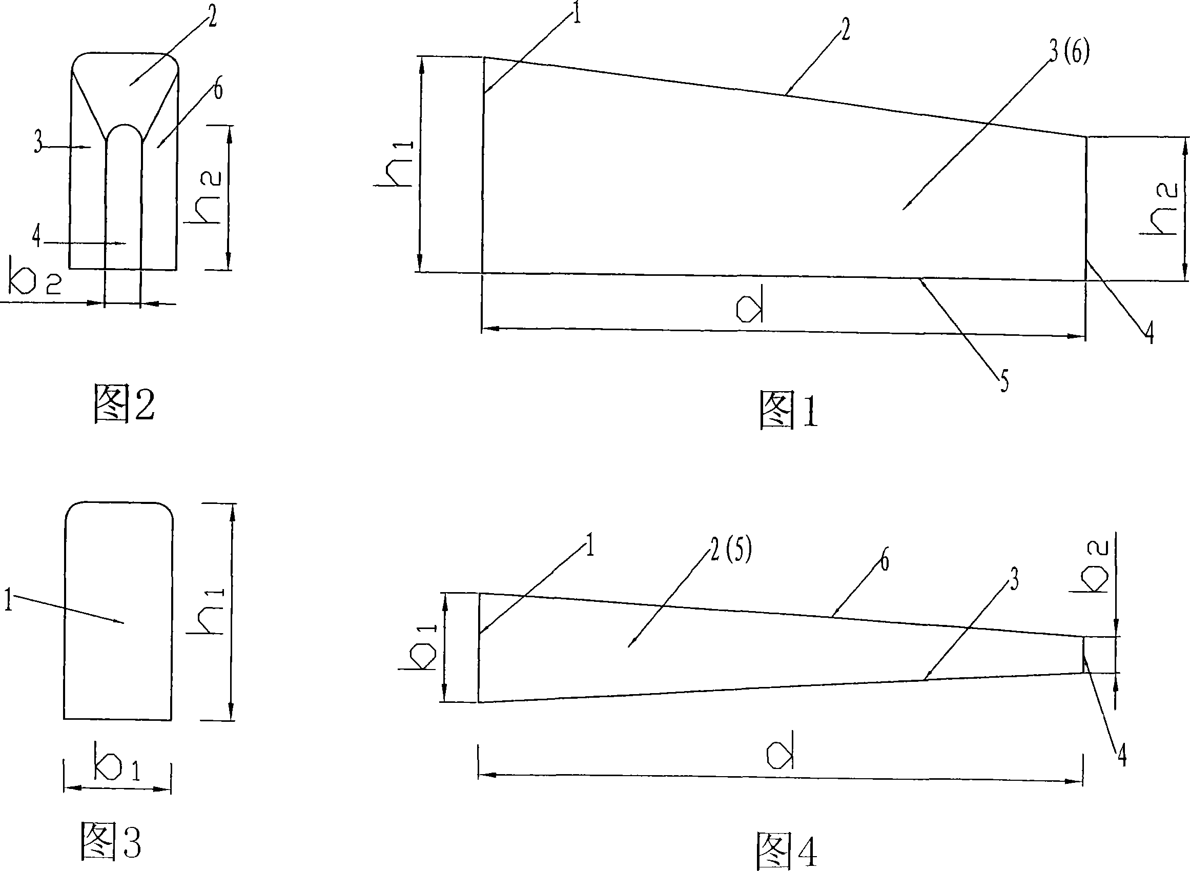
[0021] The water fin elimination tool in this embodiment is formed by pouring concrete. Its shape and structure are shown in Figure 1, Figure 2, Figure 3, and Figure 4. Located on the same horizontal plane; the front end surface 1 is a rectangular surface, the intersection of the top side of the rectangle and the two sides is connected by an arc tangent to the two intersecting sides, and the rear end surface 4 is a "∩"-shaped surface formed by a combination of a rectangle and a semicircle. The upper side 2 transitions with the right side 3 and left side 6 through arc surfaces, and the lower side 5 transitions with the right side 3 and left side 6 through edges.

[0022] According to the local topography and geological conditions, the overflow weir of the project spillway adopts a practical weir. Therefore, the relevant dimensions of the water fin elimination work are: the height h of the front face 1 1 = 7m (1.05 times the water depth at the tail of the spillway sluice pier),...

Embodiment 2

[0026] The water fin elimination tool in the present embodiment is shown in Fig. 1, Fig. 2, Fig. 3, Fig. 4, and its shape, structure are identical with the water fin elimination tool described in embodiment 1.

[0027] Because the hydrofin elimination tool described in this embodiment is used for wide-crested weirs, according to this specific project, the relevant dimensions are: the height h of the front end face 1 1 = 6m (1.03 times the water depth at the tail of the spillway sluice pier), the width b of the front end face 1 1 = 3m (the width of the spillway gate pier); the height h of the rear end face 4 2 = 4.12m (1.05 times the water depth at the installation position of the end face), the width b of the rear end face 4 2 =0.4m (0.13 times the width of the spillway pier); the distance d between the front end face 1 and the rear end face 4=17m (5.7 times the width of the spillway pier).

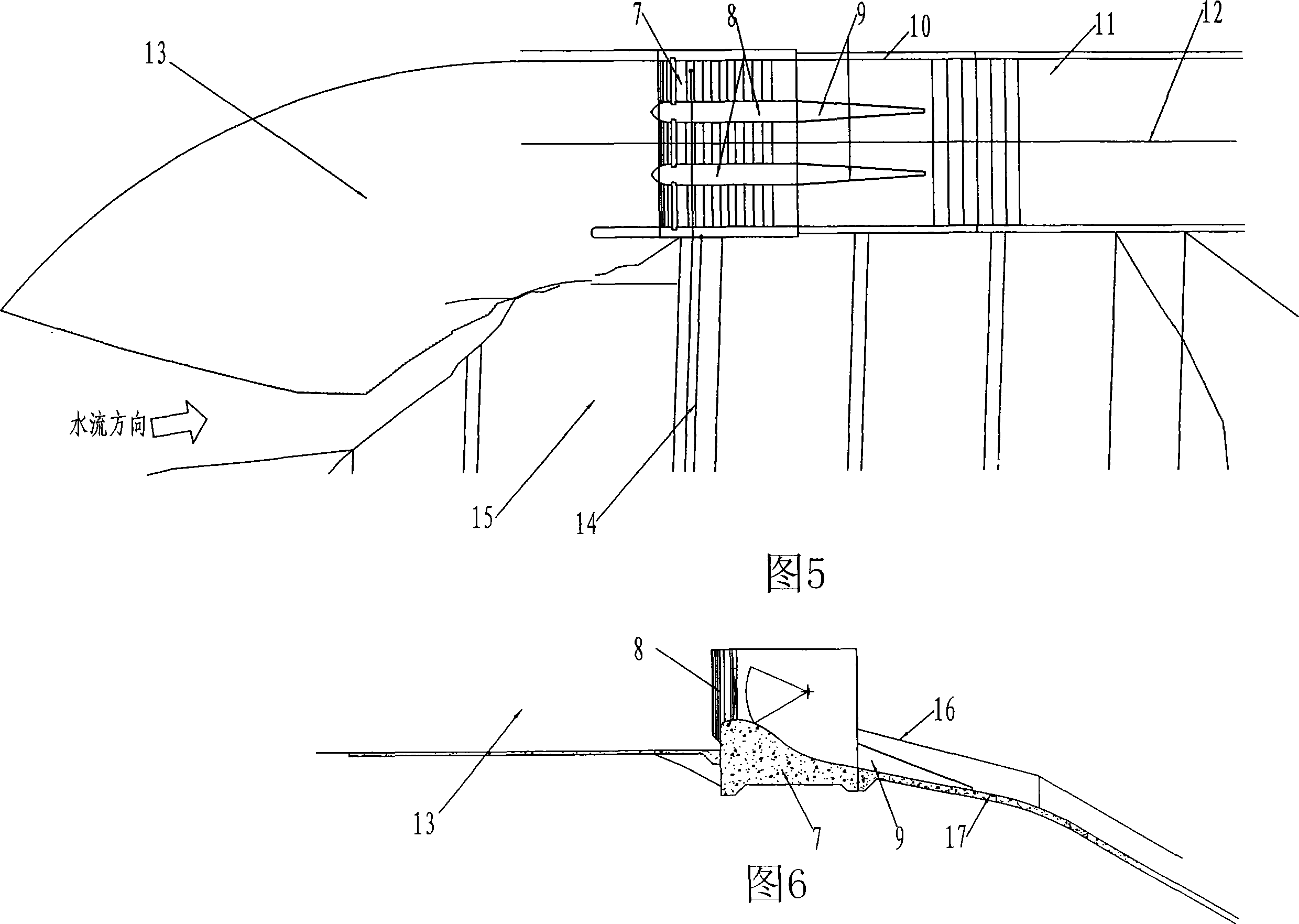
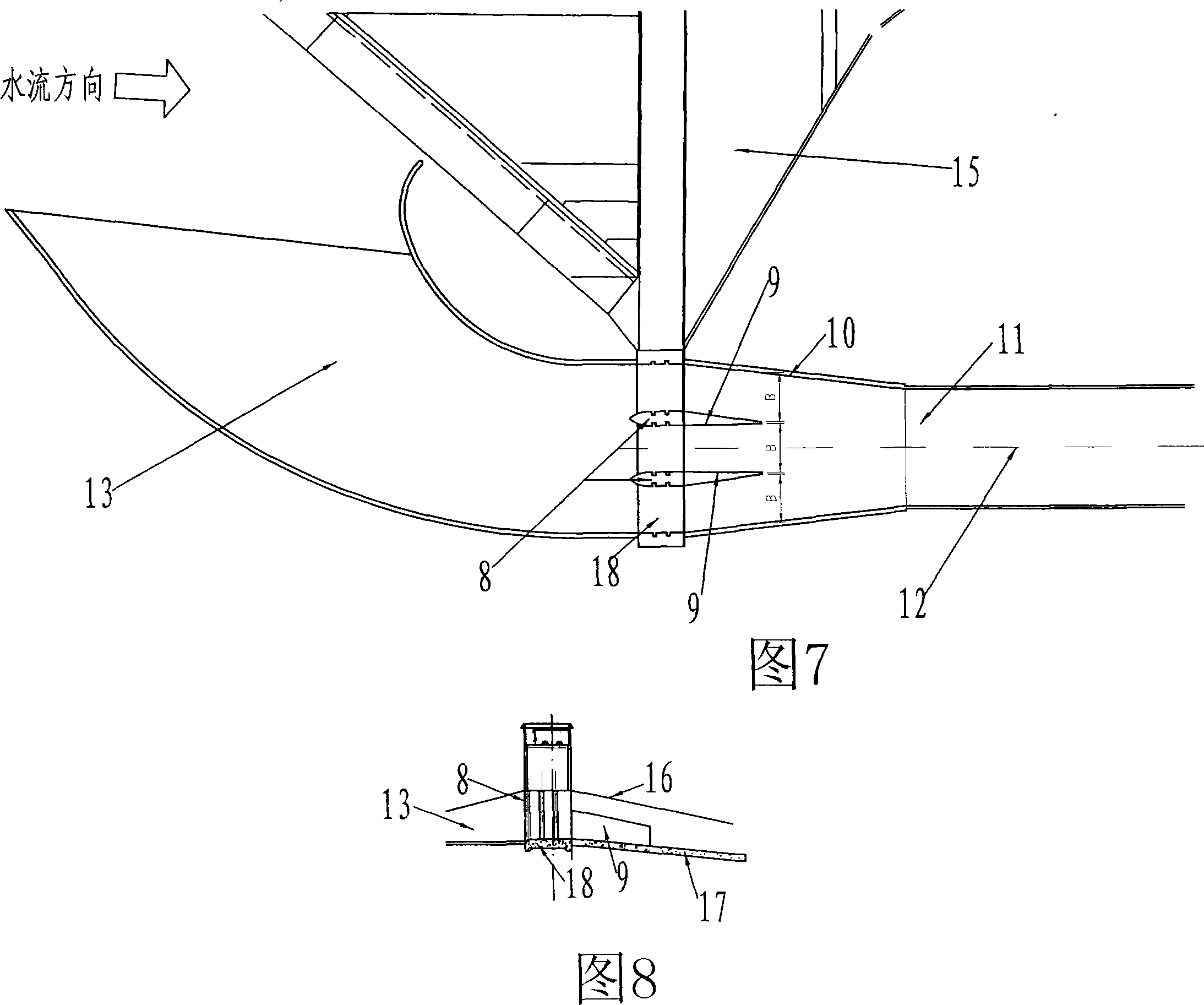
[0028] In this embodiment, two hydrofin elimination works are installed behind the ...


PUM


Abstract

A water-wring eliminating element is a quadrangular frustum pyramid structure, whose front end face and back end face are located on the same horizontal plane, wherein the height h1 of the front end face is 1-1.1 times of water depth on the tail of lock pier, and the width b1 is equal to the width of the lock pier, and the height h2 and the width b2 of the back end face are decided by the type of an over-fall dam, the height h2 of the back end face is 0.5-0.6 times of the water depth on the end face position and the width b2 is the 1 / 7-1 / 6 of the width of the lock pier if the over-fall dam is a utility dam type, and the height h2 of the back end face is 1-1.1 times of the water depth on the end face installation position, and the width b2 is the 1 / 8-1-6 of the width of the lock pier if the over-fall dam is a broad-topped dam, and the distance d between the front end face and the back end face is 5-6 times of the width of the lock pier. The water-wring eliminating element is installed on the back of the lock pier in an over-fall tunnel or a river tunnel gate dam, which can eliminate the water-wring phenomenon on the back of the over-fall tunnel or the river tunnel gate dam, and improves the water flow state in the over-fall tunnel or the river tunnel.

Description

technical field [0001] The invention belongs to drainage facilities used in water conservancy and hydropower projects, in particular to a drainage facility applied behind a spillway pier or a river gate pier to eliminate the phenomenon of water fins. Background technique [0002] In the spillway layout of water conservancy and hydropower projects, due to the large overflow width of many spillways, gate piers are required in the middle. In order to meet the structural stability requirements of gate slots and gate piers, the width of spillway gate piers is often greater than 3m, and the spillway gate hole Generally, they are steep slopes. In this arrangement, when the spillway flows, the two streams behind the pier collide with each other to form a serious water fin phenomenon, which causes the flow state behind the spillway to be disordered and increases the pressure on the side wall of the spillway. The pulsating pressure produces obvious rhombic ...

Claims


Application Information

Patent Timeline
Patent Type & Authority Applications(China)
IPC IPC(8): E02B8/06
Inventor 刁明军李斌华方旭东文俊
Owner SICHUAN UNIV
Why Eureka
Try Eureka