Electromagnetic actuating unit

An executive unit and electromagnetic technology, applied in circuits, engine components, machines/engines, etc., can solve problems such as high cost and high assembly cost

Active Publication Date: 2011-10-12
SCHAEFFLER TECH AG & CO KG
View PDF6 Cites 0 Cited by
  • Summary
  • Abstract
  • Description
  • Claims
  • Application Information

AI Technical Summary

Problems solved by technology

[0009] During the assembly of the electromagnetic actuator unit, many components must be positioned and fixed relative to each other, resulting in relatively high assembly costs, resulting in high costs

Method used


Image

  • Electromagnetic actuating unit
  • Electromagnetic actuating unit
  • Electromagnetic actuating unit

Examples


Embodiment Construction

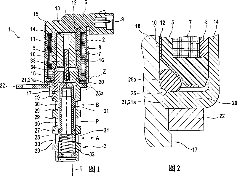
[0025] figure 1 A first embodiment of the electromagnetic actuating unit 2 according to the invention is shown, for example as a directional control valve 1 designed as a 4 / 3-way proportional valve. The reversing valve 1 has an electromagnetic actuator unit 2 and a valve section 3 .

[0026] The electromagnetic actuator unit 2 has a coil carrier 5 and a connecting element 6 integrated therewith. The bobbin 5 carries a coil 7 consisting of several windings of a suitable wire. The radially outer circumferential surface of the coil 7 is surrounded by a sleeve-shaped material layer 8 which consists of a non-magnetizable material. The material layer 8 can consist, for example, of a suitable plastic and is sprayed onto the wound coil 7 . A conductive plug-in connector 9 is accommodated in the connecting element 6 , through which the coil 7 can be supplied with current.

[0027] The coil carrier 5 is designed with an essentially cylindrical blind-hole recess 10 which is arranged ...


PUM


Abstract

The invention relates to an electromagnetic actuating unit (2) of a directional control valve (1). Provision is made here for the individual components of the actuating unit (2) to be designed, arranged and assembled such that the installation complexity and the costs incurred during production are reduced to a minimum. The electromagnetic actuating unit includes a shell, at least one armature and at least one magnet yoke, wherein the magnet yoke comprises a tubular region on which an annular region with larger diameter is connected along axial direction, in which a pole is arranged axially and movably in the magnet yoke and is moved by means of the armature; wherein the shell is made into a cup shape with a bottom, an opening is arranged on the bottom, the tubular region can extend in the shell through the opening; the outer diameter of the tubular region is at least approximately matched with the diameter of the opening, and the bottom is directly or indirectly supported on the annular region. The bottom and the tubular region are fixed with each other by means of at least one slot convergence portion. The slot convergence portion is formed by means of at least one material accumulation formed on the tubular region. The material accumulation at least partially covers one edge of the opening along radial direction, and in order to form the slot convergence portion, the material is packed on the bottom from the tubular region of the magnet yoke along the axial direction.

Description

technical field [0001] The invention relates to an electromagnetic actuator unit of a hydraulic reversing valve. Background technique [0002] In internal combustion engines, such directional valves are used, for example, to control hydraulic camshaft adjusters or switchable cam assemblies. The reversing valve consists of an electromagnetic actuator and a valve section. The valve section is the hydraulic part of the directional control valve, on which at least one inlet connection, at least one working connection and a tank connection are formed. Certain joints of the valve section can be hydraulically connected to each other by means of the electromagnetic actuator unit, so that the pressure medium flow can be diverted. [0003] In the case where the reversing valve is used to control the camshaft adjuster, it is normally designed as a three-position four-way proportional reversing valve. Such a proportional valve is disclosed, for example, in DE 199 56 160 . In this ca...

Claims


Application Information

Patent Timeline
Patent Type & Authority Patents(China)
IPC IPC(8): F16K31/06F01L1/46
CPCF01L2001/34426F01L2001/3443F16K31/06F16K31/0675Y10T403/4966Y10T137/5987Y10T137/6007Y10T137/86622F01L1/46
Inventor C·罗斯J·格勒舍尔
Owner SCHAEFFLER TECH AG & CO KG
Why Eureka
Try Eureka