Door handle mounting structure

A technology for door handles and structures, which can be used in the direction of handle connections, lock casings, door/window accessories, etc., and can solve problems such as door sags

Active Publication Date: 2012-02-22
KAWAJUN KK
View PDF1 Cites 0 Cited by
  • Summary
  • Abstract
  • Description
  • Claims
  • Application Information

AI Technical Summary

Problems solved by technology

However, even if such a material is used, the operator has to fasten it more strongly in order to securely fix it. In this case, there is a problem of deformation such as denting of the door.

Method used


Image

  • Door handle mounting structure
  • Door handle mounting structure
  • Door handle mounting structure

Examples


Embodiment Construction

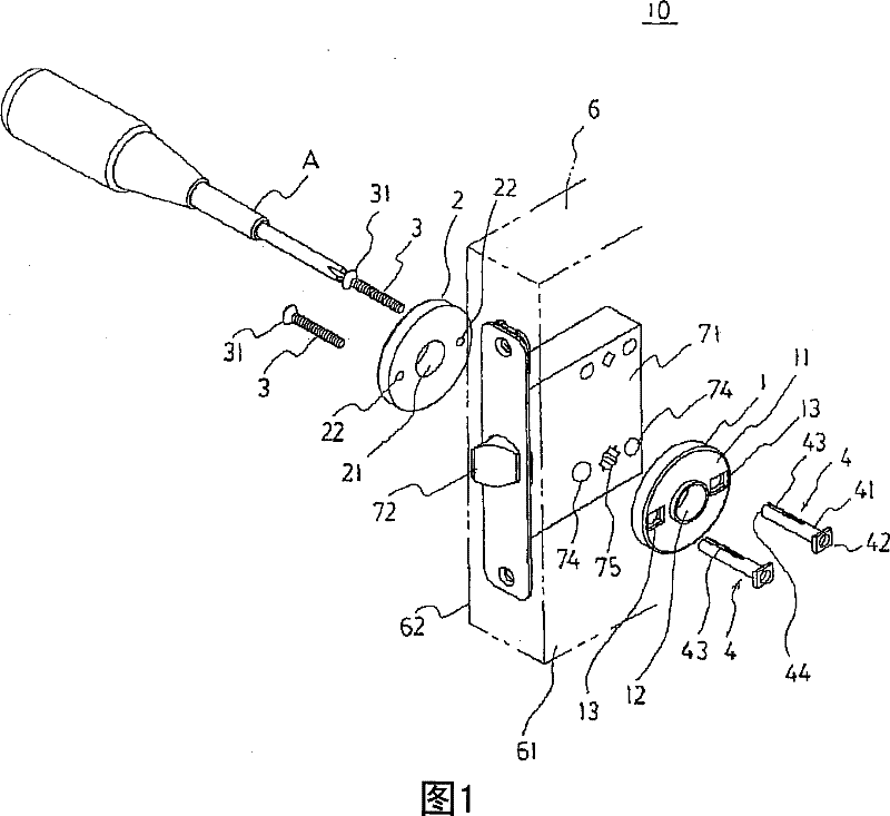
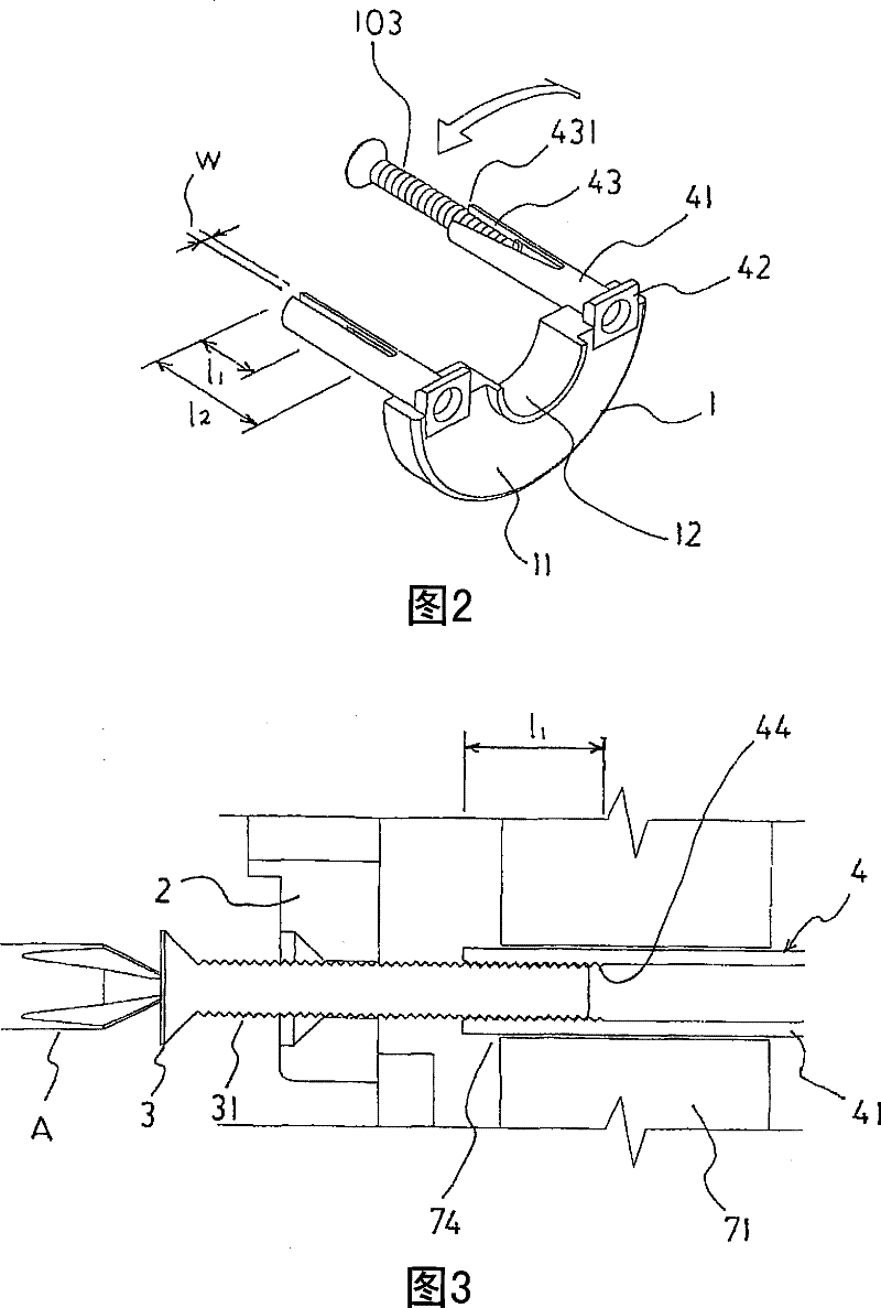
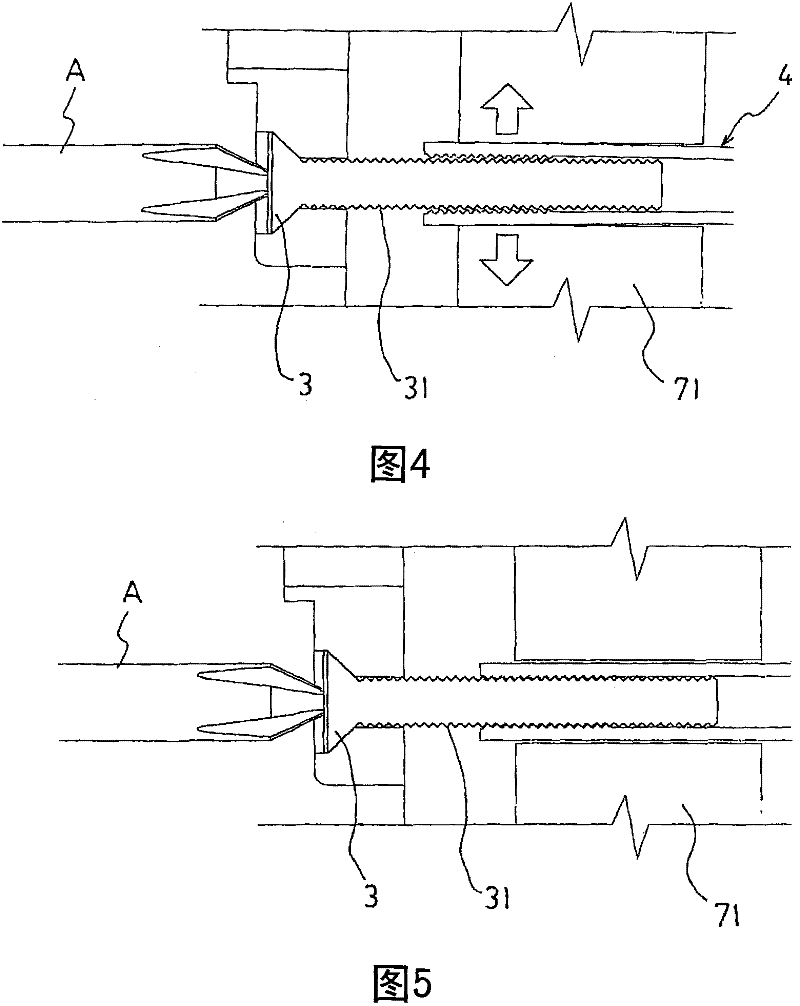
[0023] Below, will refer to Figure 1 to Figure 6 The door handle mounting structure (hereinafter, simply referred to as "mounting structure") according to the first embodiment of the present invention will be described in detail. figure 1 It is a figure explaining the situation of installing the installation body structure on the door, figure 2 It is a diagram showing the state where a screw is screwed into the threaded hole for screw thread connection of the screw sleeve, image 3 It is a schematic diagram showing the initial state of a small screw screwed into the threaded hole for screw thread connection of the screw sleeve, Figure 4 It is a schematic diagram showing the meshing state of the screw when the small screw is fastened and the slit is opened, Figure 5 is to indicate that the screw is from Figure 4 The state returns a sketch of the meshing state of a thread, Figure 6 is a plan view showing a part of the mounting structure through a section, Figure 8 It...


PUM


Abstract

To provide a door handle attachment structure which prevents overfastening of a screw. A attachment structural body 10 comprising a first seat 1 disposed on one side 61 of a door 6, the first seat 1 being provided with a boss 4 having a screw-mounting hole; a second seat 2 disposed on the other side 62 of the door 6, the second seat 2 being provided with a screw-inserting hole 22 in a position opposing to the boss 4; a screw 3 for integrally connecting the first seat 1 and the second seat 2, screwed in the screw-mounting hole through the screw-inserting hole 22 of the second seat 2; and a pair of door handles, one disposed on the outside of the first seat 1 and the other disposed on the outside of the second seat 2, each being connected through handle-attaching holes respectively provided in the first seat 1 and the second seat 2; the boss 4 having a slit 43 with a length larger than the screw along the direction of the axis from the boss end 44 on the screw inserting side.

Description

technical field [0001] The present invention relates to a mounting structure of a door handle such as a lever handle freely rotatably mounted at a given position of a door. Background technique [0002] An example of a conventional door handle mounting structure is Figure 8 As shown, it includes: a screw sleeve 104 with a head 141, which is arranged on an outer surface 161 of the door 106 and has a threaded hole for small screw thread connection (in Figure 8 can not be seen in); the disc-shaped base body 101 (the first base), which includes the first handle mounting hole 112 and the mounting holes 113 of the two screw sleeves 104 with heads; the second base 102, It is arranged on the other outer surface 162 of the door 106 corresponding to the base body 101 and is provided with two small screw insertion holes 122 and a second handle installation hole 121 at the positions facing the screw sleeve 104 and the first handle installation hole 112 respectively. 2 small screws 103...

Claims


Application Information

Patent Timeline
Patent Type & Authority Patents(China)
IPC IPC(8): E05B3/00E05C1/00
CPCE05B3/00E05B9/08E05B15/1614E05B15/1635E05B2009/004
Inventor 松本育也
Owner KAWAJUN KK
Why Eureka
Try Eureka