Brake lining arrangement for disc brakes

A technology of disc brakes and brake linings, applied in the direction of brake components, brake types, mechanical equipment, etc.

Active Publication Date: 2011-04-13
LUCAS AUTOMOTIVE GMBH
View PDF8 Cites 4 Cited by
  • Summary
  • Abstract
  • Description
  • Claims
  • Application Information

AI Technical Summary

Problems solved by technology

Furthermore, after the riveting operation, it is not possible to determine with sufficient reliability by visual inspection whether the cross-section of the protrusion has been enlarged sufficiently and a suitably rigid connection between the two parts has been produced

Method used


Image

  • Brake lining arrangement for disc brakes
  • Brake lining arrangement for disc brakes
  • Brake lining arrangement for disc brakes

Examples


Embodiment Construction

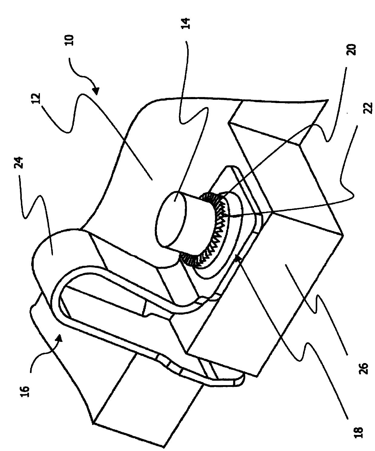
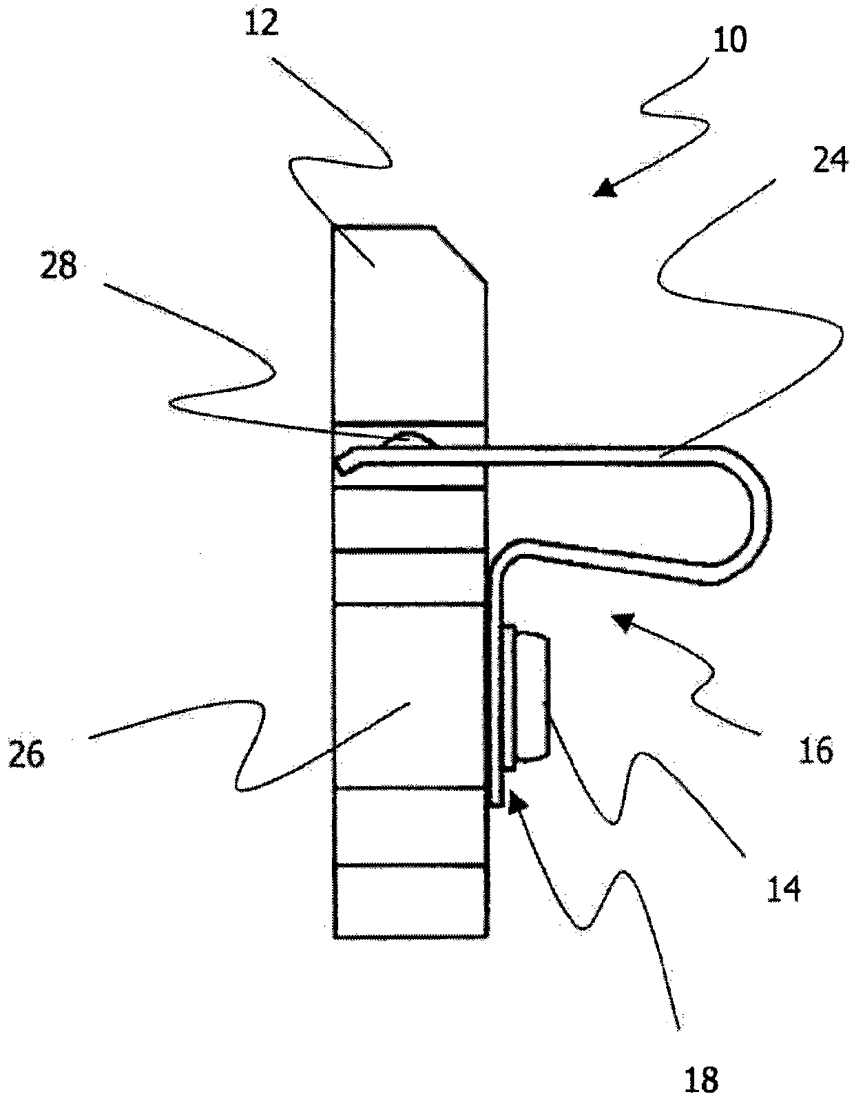
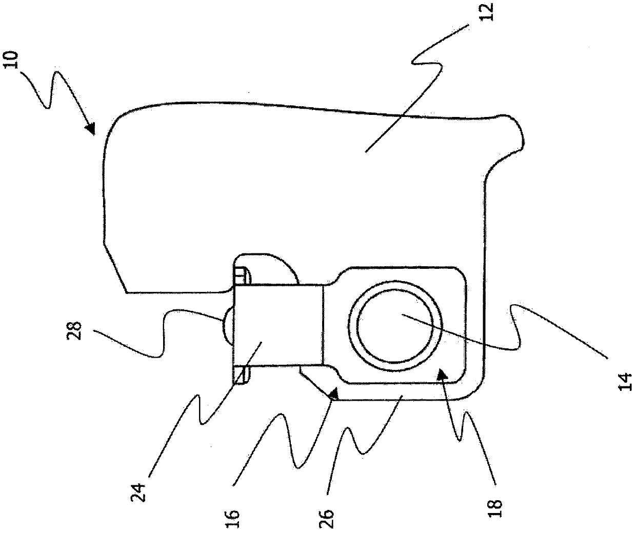
[0017] figure 1 The brake lining arrangement 10 with the spring element 16 and the spring pin 14 arranged on the back of the brake lining 12 is shown after the riveted fastening of the spring pin 14 . from figure 1 The fastening part 18 of the spring element 16 can be seen more clearly in the figure, which fastening part 18 has an irregular surface structure 22 and / or a profile at least in sections around the receiving opening 20 . The surface structure can in particular be configured in the form of sawtooth, knurling or fluting. Further provided on the spring element 16 is an arcuate portion 24 , by means of which the brake lining arrangement 10 can be fastened to a brake piston (not shown) of a disc brake.

[0018] figure 1 Also shown is a protrusion 26 to which the spring element 16 can be fastened by means of the spring pin 14 . It is more evident that the end region of the arcuate portion 24 protrudes into the cross-section of the brake lining 12 above the protrusion ...


PUM


Abstract

The invention relates to a brake lining arrangement (10) for disk brakes having at least one spring journal (14) arranged on the back of the brake lining (12) and a spring element (16) that can be coupled to said spring journal. The spring element (16) comprises a fastening section (18) with a receiving opening (20) for receiving the spring journal (14), wherein on the surface (22) of the fastening section (18) of the spring element (14) facing away from the brake lining (12) a profiling is configured, which engages with the spring journal (14) when it is plastically deformed for fixing the spring element (16) and secures the spring element (16) in a predetermined position.

Description

technical field [0001] The invention relates to a brake lining arrangement for a disc brake, which has at least one spring pin arranged on the back of the brake lining and a spring element which can be coupled with the spring pin, wherein the The spring element has a fastening part with a receiving opening for receiving the spring pin. Background technique [0002] Such a device is known, for example, from EP 0 609 245 B1. In this brake lining device, in order to fasten the stop spring whereby the brake lining plus the plate-shaped brake lining carrier is held in the caliper device, a protrusion is formed on the lining rear plate, the protrusion Protrude from the plane of the board. In order to fasten the retaining spring to the lining rear plate, the retaining spring has an opening through which the retaining spring can be placed on the protrusion and moved into the correct angular position. Once the retaining spring is in the correct position, the protrusion is riveted,...

Claims


Application Information

Patent Timeline
Patent Type & Authority Applications(China)
IPC IPC(8): F16D65/097
CPCF16D65/0976F16D65/0979F16D65/0975F16D65/0974F16D65/0973F16D65/0977F16D65/0978
Inventor 克劳斯·罗特迪尔克·黑斯
Owner LUCAS AUTOMOTIVE GMBH
Why Eureka
Try Eureka