
Pipe type incandescent lamp

A technology for incandescent lamps and tubes, applied in the direction of incandescent lamps, incandescent lamp parts, electrical components, etc., can solve the problems of inconsistent heating of printing media, no positioning part, and inability to configure tube-type incandescent lamp extensions, etc., to ensure strength, Prevent damage, prevent unfixed effect

Active Publication Date: 2008-07-16
USHIO DENKI KK
View PDF1 Cites 2 Cited by
  • Summary
  • Abstract
  • Description
  • Claims
  • Application Information

AI Technical Summary

Problems solved by technology

[0024] However, the tube-shaped incandescent lamp described in Patent Document 1 does not have a positioning portion, and even if the end of the tube-shaped incandescent lamp is fixed by a fixing member and arranged inside the fixing roller, the tube-shaped incandescent lamp cannot be arranged and fixed. The central axis of the roller is extended
If the tube-shaped incandescent lamp cannot be arranged on the central axis of the fixing roller, there will be the following problems, that is, the heating of the printing medium passing through the outer peripheral surface of the fixing roller will become inconsistent, and the toner applied on the printing medium will appear to be fixed. parts and unfixed parts

Method used


Image

  • Pipe type incandescent lamp
  • Pipe type incandescent lamp
  • Pipe type incandescent lamp

Examples


Embodiment Construction

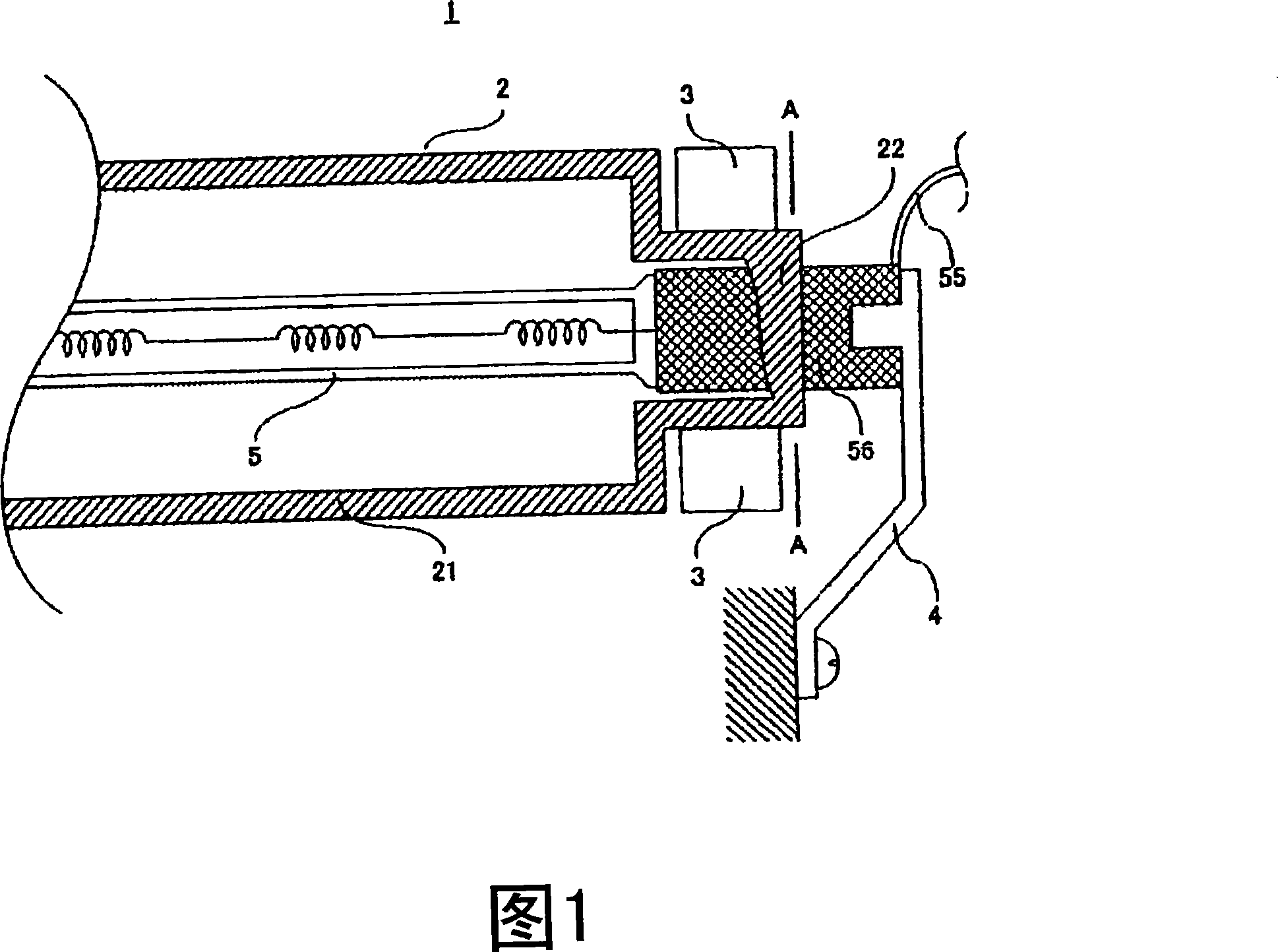
[0074] An example of a printer fixing device 1 according to the present invention will be described with reference to FIG. 1 .

[0075] FIG. 1 is a side view of a longitudinal end portion of a fixing device 1 of a printer, and a part of a fixing roller 2 is removed to illustrate the inside thereof. The same reference numerals are assigned to the same components as those shown in FIG. 12 . Also, the pressure roller is omitted.

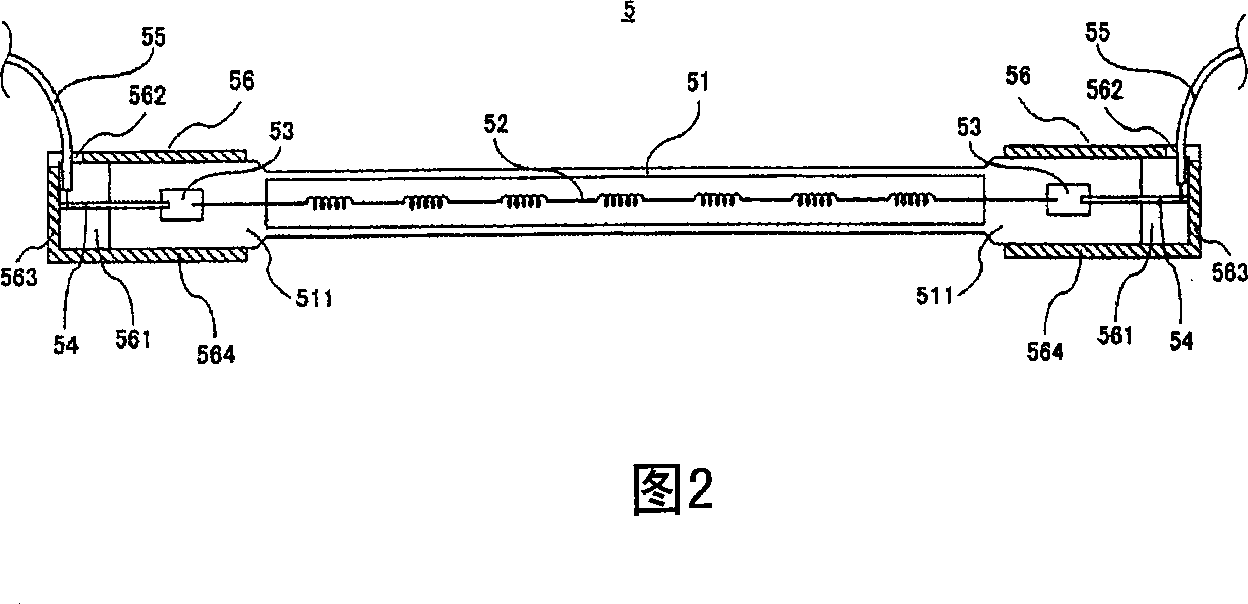
[0076] The printer fixing device 1 includes a pressure roller (not shown), a fixing roller 2 , a rotation gear 3 , a tube-shaped incandescent lamp 5 , and a fixing member 4 . The description about the pressure roller is omitted.

[0077] A cylindrical fixing roller 2 is disposed in the printer fixing device 1 . The fixing roller 2 includes: a cylindrical radially enlarged portion 21 that expands in the radial direction; a cylindrical radially reduced portion 22 whose end portion is radially reduced relative to the radially enlarged portion 21 in the ...


PUM


Abstract

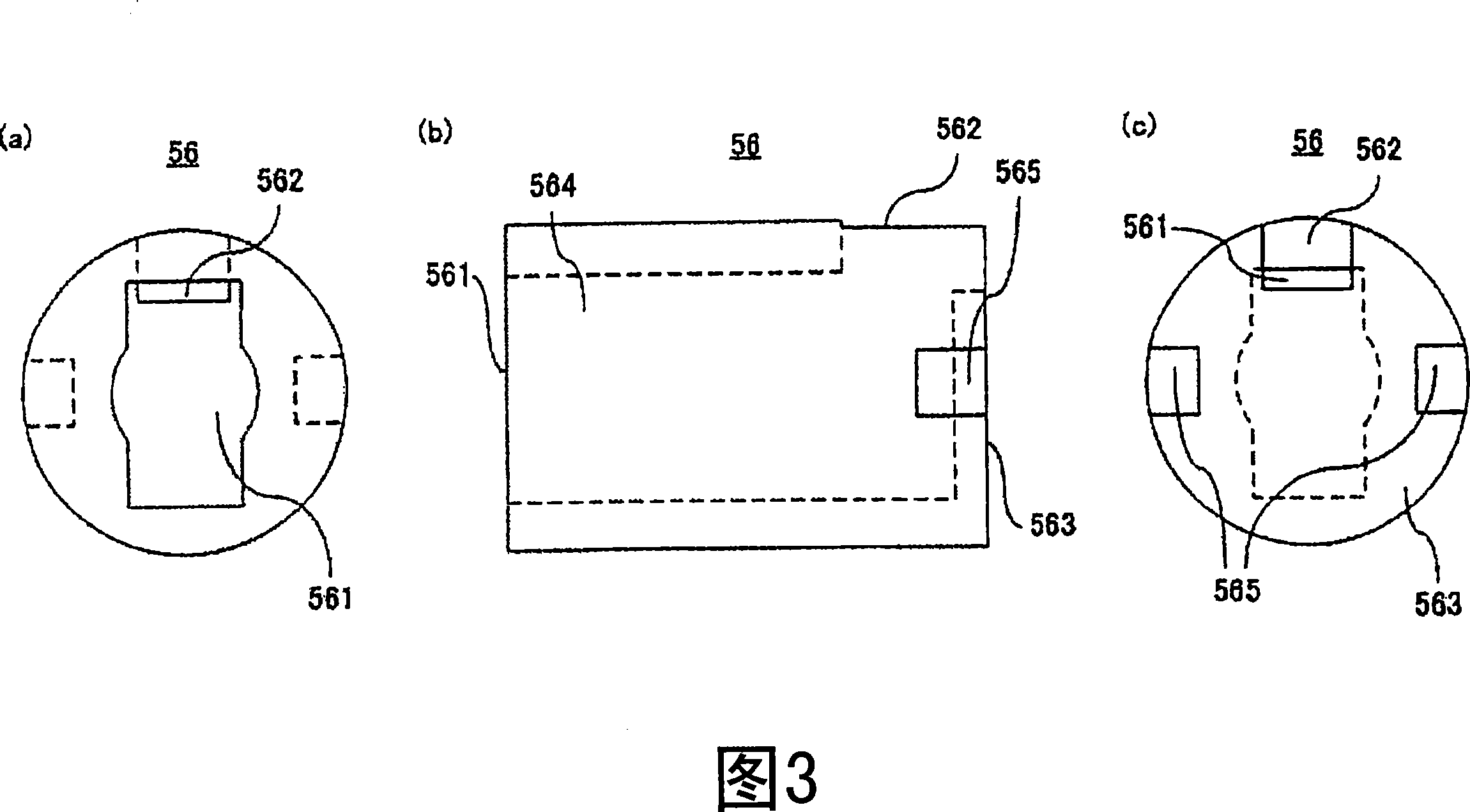
The aim of the present invention is to provide a tube-shaped incandescent lamp with positioning part which does not project along the tube axis direction but can be set on the central axis of a fixing roller. The tube-shaped incandescent lamp includes: tube-shaped incandescent packaging body, containing sealing parts on two ends; lamp holder, locating on the packaging body; conductor, educing from the lamp holder. The lamp is characterized in that the lamp holder is equipped with an opening part combining with the sealing part, and has an deduced hole in the direction crossing with the opening part; a longest diagonal formed along the lamp holder opening forms required wall thickness, and forming a convex part within a cylinder-shaped range formed along most outer diameter of the lamp holder after increasing the wall thickness of the diagonal, by means of making the convex part leave the deduced hole to set the positioning part.

Description

technical field [0001] The invention relates to a tubular incandescent lamp used in a printer fixing device. Background technique [0002] The printer fixing device 1 will be described using FIG. 10 . FIG. 10 is a cross-sectional view perpendicular to the longitudinal direction of the printer fixing device 1 . [0003] The printer fixing device 1 abuts a cylindrical pressure roller 6 and a cylindrical fixing roller 2 arranged in parallel, and a tubular incandescent lamp 5 is arranged on the central axis of the fixing roller 2 . The pressure roller 6 and the fixing roller 2 are held by an unillustrated rotation gear or an unillustrated drive unit so that their central axes do not move. When the printer is in operation, the cylindrical pressure roller 6 and the cylindrical fixing roller 2 rotate around their respective central axes while being in contact with each other by a drive unit (not shown). During printing, since the printing medium passes through the abutting surfa...

Claims


Application Information

Patent Timeline
Patent Type & Authority Applications(China)
IPC IPC(8): H01K1/46
Inventor 生岛和之山本敏幸
Owner USHIO DENKI KK
Learn More