
Photon crystal optical fibre coupling method and its coupling apparatus

A photonic crystal fiber and coupling device technology, which is applied in the coupling of optical waveguides, cladding fibers, optical waveguides and light guides, etc., can solve problems such as affecting the quality of optical fiber connections, and achieve easy mass production and application, high coupling efficiency, and high strength. effect of connection

Inactive Publication Date: 2008-07-09
GUANGXUN SCI & TECH WUHAN
View PDF0 Cites 18 Cited by
  • Summary
  • Abstract
  • Description
  • Claims
  • Application Information

AI Technical Summary

Problems solved by technology

The reason why this kind of method can be used is that pure silica fiber has a high absorption peak at 1060nm wavelength, so the CO emission wavelength at this wavelength can be used 2 The laser cleans the end faces of the two optical fibers to be connected and fuses them; in addition, the CO 2 Lasers are easy to control the shape and power of the beam, but this method is more suitable for splicing large-aperture photonic crystal fibers. Factors such as size difference and lateral offset, fiber end face filling, condensed liquid trapped in the air capillary, fusion power and fusion time will seriously affect the connection quality of the fiber

Method used

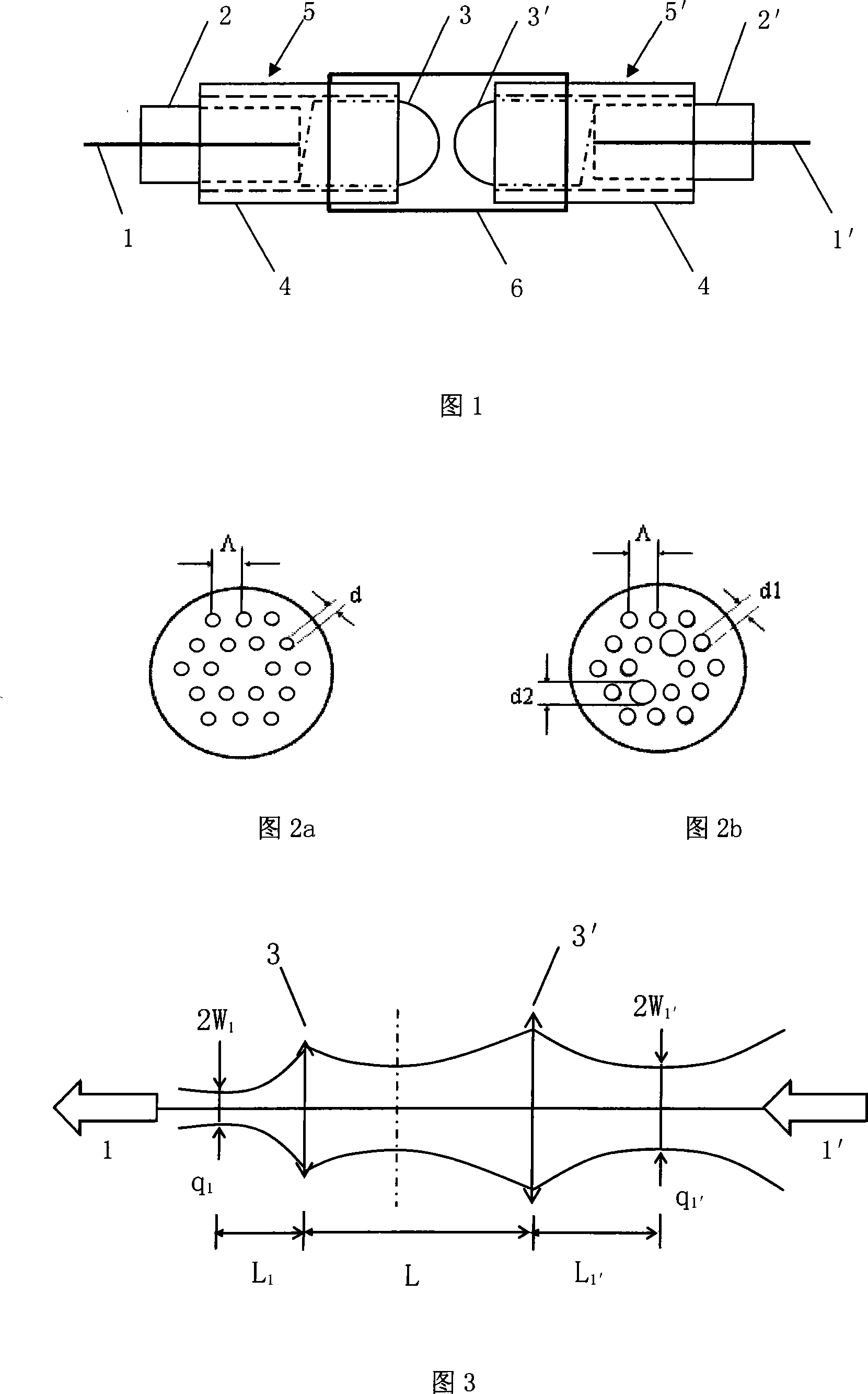

Image

  • Photon crystal optical fibre coupling method and its coupling apparatus
  • Photon crystal optical fibre coupling method and its coupling apparatus
  • Photon crystal optical fibre coupling method and its coupling apparatus

Examples


Embodiment Construction

[0035] The photonic crystal fiber coupling method and its coupling device of the present invention will be described in detail below in conjunction with the accompanying drawings and embodiments.

[0036] The manufacturing method of the coupling device of making photonic crystal fiber described in claim 1, is characterized in that, comprises the following steps:

[0037]The first step is to determine the equivalent mode field radius with reference to the specific parameters of the photonic crystal fiber to be connected:

[0038] The specific parameters of the photonic crystal fiber can be obtained by the specific measurement of the fiber to be connected, which can be directly provided by the manufacturer in most cases. For example, Corning company gives an empirical formula about the equivalent core radius and hole spacing: equivalent core radius = hole spacing / 1.732, then we can measure the specific mode field radius, or according to the equivalent mode field The theoretic...


PUM


Abstract

The invention relates to a photonic crystal fiber coupling method and a coupling device thereof. The method comprises the following steps of: determining the equivalent mold field radius of a photonic crystal fiber to be connected according to the specific parameters; selecting a corresponding extender lens and a focusing lens element according to the specific parameters of the photonic crystal fiber to be connected, and calculating the lens coupling optical path to determine a group of distance values for instructing the actual adjusting process; and adjusting the actual coupling optical path according to the distance parameters calculated in step 2 to obtain the minimal loss state, and carrying out a packaging connection. The device comprises a first and a second pins for fixing corresponding one ends of the photonic crystal fiber and a corresponding coupling optical fiber; the extender lens and the focusing lens arranged between the first and the second pins; and an engagement portion for respectively sheathing the first pin and the extender lens as well as the focusing lens and the second pin at the outer periphery of the engagement portion to package the elements; and an outer sleeve for entirely packaging and fixing the elements. The invention has the advantages of simple connection process, high optical fiber coupling efficiency and high connection strength and can eliminate loss resulting from mismatch of mold fields.

Description

technical field [0001] The invention relates to an optical fiber coupling device. In particular, it relates to a low-loss, high-intensity photonic crystal fiber coupling method and a coupling device that can connect a photonic crystal fiber with periodically arranged air holes in the cladding and a connected fiber. Background technique [0002] Photonic crystal fiber is a fiber with periodically arranged air holes in the cladding, also known as microstructure fiber or holey fiber, which can be divided into two types: index-guided type and bandgap waveguide type. The transmission mechanism of the former is improved total internal reflection. The latter utilizes the photonic bandgap effect. Because it can achieve characteristics such as unlimited single-mode transmission, large dispersion, and high nonlinearity that cannot be achieved by previous core / cladding optical fibers, it is regarded as a potential substitute for various functional optical fibers or optical fibers for ...

Claims


Application Information

Patent Timeline
IPC IPC(8): G02B6/26G02B6/02
Inventor 张璐胡强高张玓江山
Owner GUANGXUN SCI & TECH WUHAN
Learn More