
Diesel engine fuel injector mounting structure

A technology for mounting structures and fuel injectors, applied to machines/engines, fuel injection devices, charging systems, etc., can solve the problems of increasing manufacturing costs, increasing the number of parts, increasing the number of high-pressure sealing surfaces, and achieving a simple structure Effect

Inactive Publication Date: 2008-07-09
WUXI KIPOR POWER CO LTD
View PDF0 Cites 10 Cited by
  • Summary
  • Abstract
  • Description
  • Claims
  • Application Information

AI Technical Summary

Problems solved by technology

[0002] In the existing four-valve diesel engine technology, the high-pressure oil circuit is usually formed by the high-pressure oil pipe supplying fuel oil to the injector through the seal on the cylinder head cover and connected to the injector, so when disassembling or repairing the cylinder head cover The high-pressure fuel pipe must be removed first before the cylinder head cover can be removed for internal parts. This will not only increase the workload of the workers, but may also damage the high-pressure fuel pipe and cause fuel leakage accidents.
Another method is to use the high-pressure oil pipe to connect the fuel injector fixed on the cylinder head through the transitional high-pressure oil chamber installed on the cylinder head, so as to increase the number of parts and the number of high-pressure sealing surfaces, and increase the Increased manufacturing costs and increased risk of high-pressure fuel leakage

Method used


Image

  • Diesel engine fuel injector mounting structure
  • Diesel engine fuel injector mounting structure
  • Diesel engine fuel injector mounting structure

Examples


Embodiment Construction

[0013] Below the present invention will be further described in conjunction with the embodiment in the accompanying drawing:

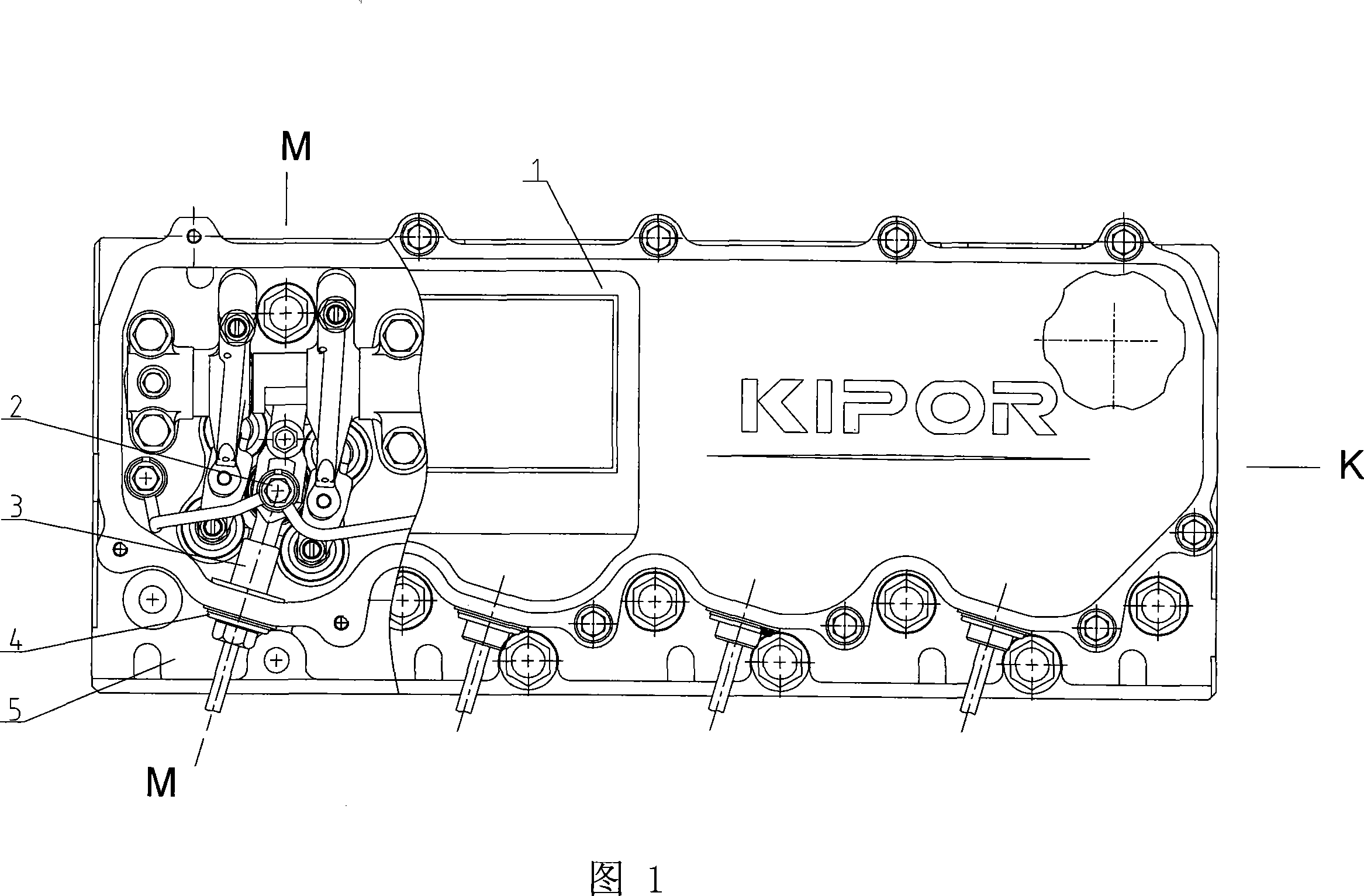
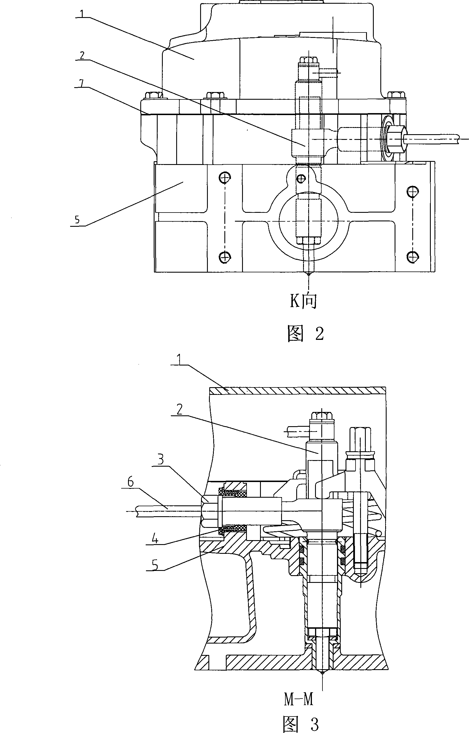
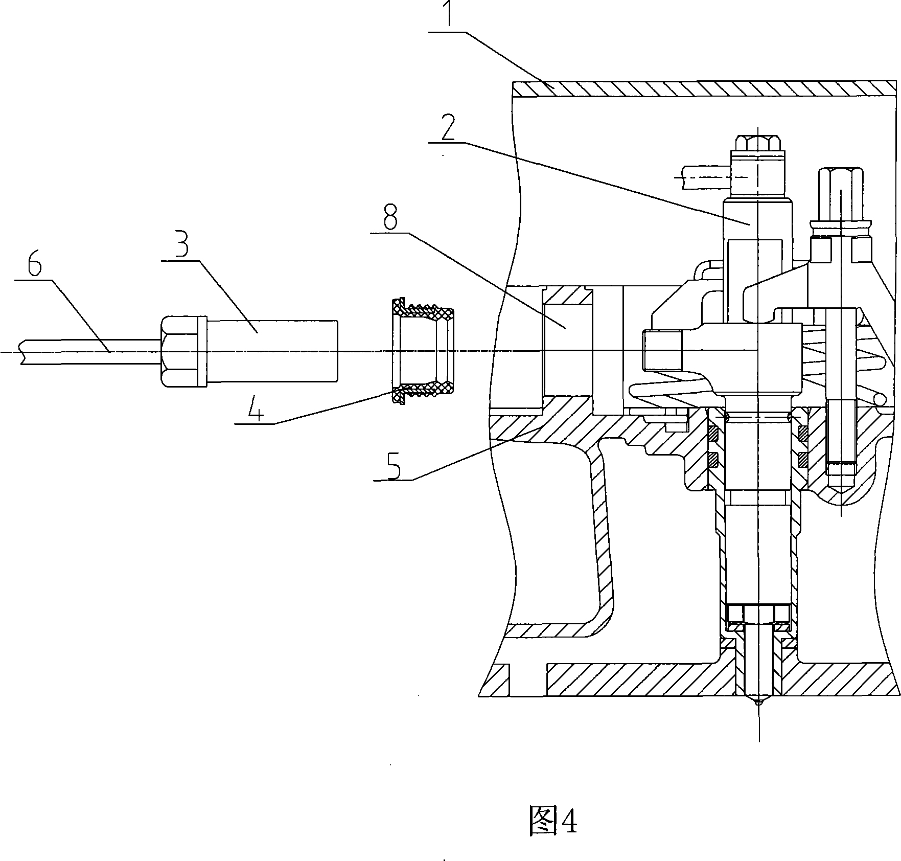
[0014] The present invention is mainly made up of cylinder head cover 1, fuel injector 2, high-pressure oil pipe joint 3, seal 4, cylinder head 5, high-pressure oil pipe 6 and sealing ring 7, and cylinder head 5 is provided with high-pressure oil pipe hole 8.

[0015] The cylinder head 5 of the present invention, the cylinder head cover 1 and the sealing ring 7 placed between the cylinder head 5 and the cylinder head cover 1 are fixed to the cylinder head 5 by bolts to form a sealed valve control chamber. A fuel injector 2 is installed in the middle of the four valves (two exhaust valves and two intake valves), and the fuel injector 2 is placed in a sealed valve control chamber. A high-pressure fuel pipe hole 8 is provided on the cylinder head 5 corresponding to the oil inlet of the fuel injector 2, and a seal 4 is installed at the high-pressure fuel p...


PUM


Abstract

The invention relates to an installation structure for a diesel injector, in particular belongs to the technical field of a power plant. An oil atomizer is arranged in a sealed valve control cabin consisting of a cylinder head, a seal ring and a cylinder cover hood, and is fixed on the cylinder head. The invention is characterized in that: the cylinder head is provided with a high pressure pipe hole; a high pressure pipe joint is connected with the oil atomizer fixed on the cylinder head through the high pressure pipe hole; a sealing element is arranged between the high pressure pipe joint and the high pressure pipe hole. The structure of the invention is simple, compact and rational; the cost of manufacture is reduced; the invention is overhauled conveniently; just the cylinder cover hood is needed to be removed without needing to remove the fuel injection pipe components when the internal components of the cylinder cover hood are maintained; when the invention runs at a low speed, the cylinder cover hood is not required to be covered, and whether the fuel injection pipe joint leaks oil can be observed directly.

Description

technical field [0001] The invention relates to an installation structure of a fuel injector for a diesel engine, and in particular belongs to the technical field of power devices. Background technique [0002] In the existing four-valve diesel engine technology, the high-pressure oil circuit is usually formed by the high-pressure oil pipe supplying fuel oil to the injector through the seal on the cylinder head cover and connected to the injector, so when disassembling or repairing the cylinder head cover For internal parts, the high-pressure fuel pipe must be removed before the cylinder head cover can be removed. This will not only increase the workload of the workers, but also may damage the high-pressure fuel pipe and cause fuel leakage accidents. Another method is to use the high-pressure oil pipe to connect the fuel injector fixed on the cylinder head through the transitional high-pressure oil chamber installed on the cylinder head, so as to increase the number of parts...

Claims


Application Information

Patent Timeline
IPC IPC(8): F02M61/14F02M55/02
Inventor 肖亨琳
Owner WUXI KIPOR POWER CO LTD
Learn More