Blaze-folding corner structure for weakening furnace outlet remainder rotation

A furnace exit and refraction angle technology, applied in the field of refraction angle structure, can solve problems such as drop, adverse effects of pulverized coal, and influence on boiler combustion stability, so as to reduce the flow area, strengthen the racemization effect, and increase the flue gas flow rate Effect

Inactive Publication Date: 2008-06-25
XI AN JIAOTONG UNIV
View PDF0 Cites 3 Cited by
  • Summary
  • Abstract
  • Description
  • Claims
  • Application Information

AI Technical Summary

Problems solved by technology

The first method is that after the anti-cut wind is adopted, the rotation intensity of the flow field used to organize the combustion in the furnace will decrease, which will affect the stability of the boiler combustion. Excessive anti-cut braking may cause residual rotation in the opposite direction. In addition, the residual rotation in the folding Below the flame angle is still the opportunity for the pulverized coal to burn out, and premature braking may have an adverse effect on the burnout of the pulverized coal
The second method, due to the limitation of the actual structure of the boiler, has certain limitations, and it is difficult to obtain a more ideal depolarization effect

Method used


Image

  • Blaze-folding corner structure for weakening furnace outlet remainder rotation
  • Blaze-folding corner structure for weakening furnace outlet remainder rotation

Examples


Embodiment 1

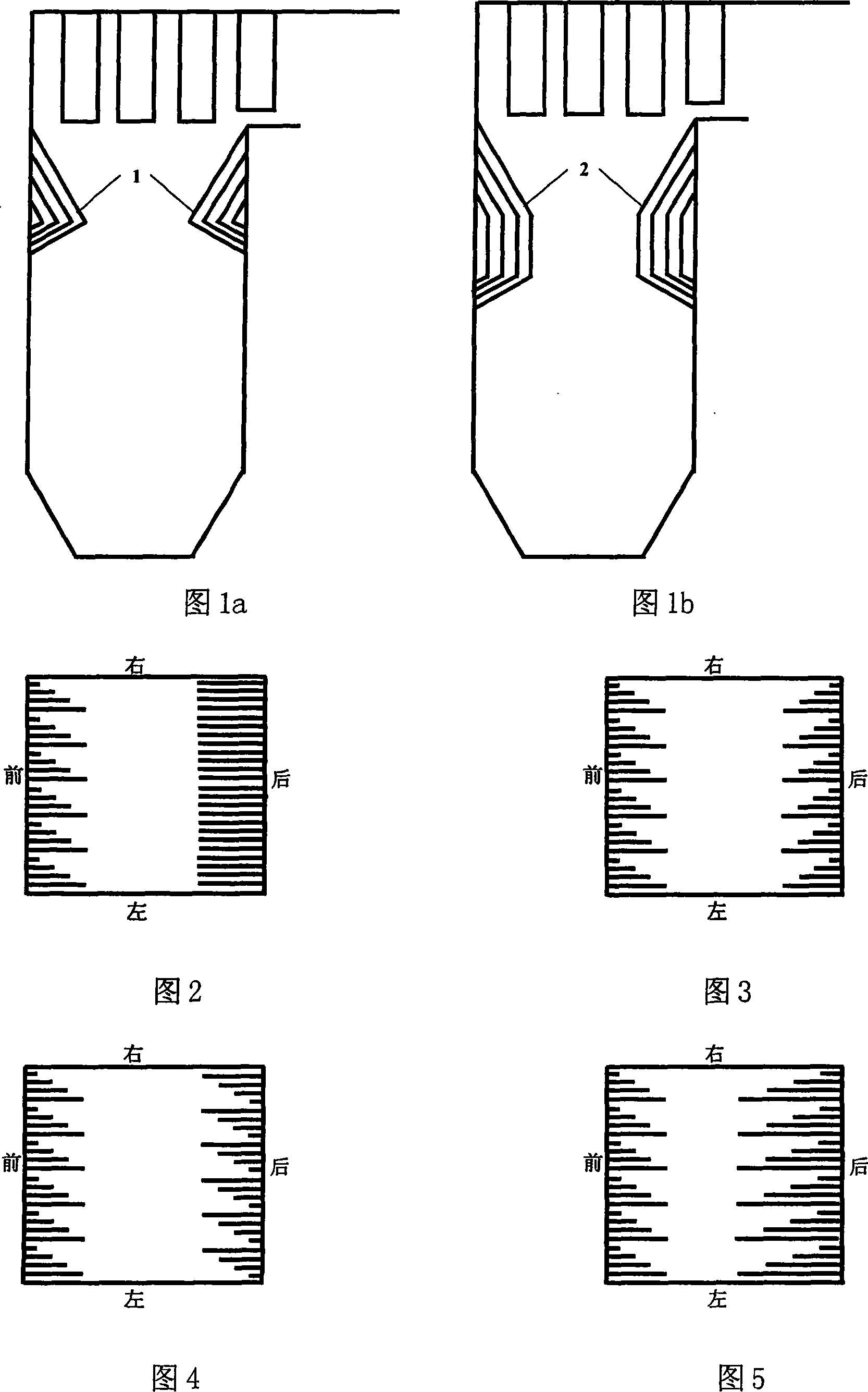
[0018] Embodiment 1: Referring to Figure 2, this embodiment retains the traditional flame bending angle for the rear wall, and bends the water-cooled wall tube of the front wall opposite to the rear wall to form a triangular or trapezoidal flame bending angle 1 to form a flame bending angle The water wall tubes in corner 1 are divided into n (n≥1) groups, and each group has at least two water wall tubes. The water-cooled wall tubes inside each group are bent in turn from right to left, and the depth of insertion into the furnace increases sequentially to form alternate staggered tube rows.

Embodiment 2

[0019] Embodiment 2, referring to Fig. 3, in this embodiment, the water-cooled wall tubes on the front and rear furnace walls are all bent to form a triangular or trapezoidal folded flame angle 1, and the water-cooled wall tubes forming the flame folded angle 1 are divided into n(n ≥1) group, each group of water wall tubes shall be at least two. The water-cooled wall tubes inside each group are bent in turn from right to left, and the depth of insertion into the furnace increases sequentially to form alternate staggered tube rows. The water-cooled wall tube rows forming the flame angle on the front and back furnace walls are symmetrically distributed.

Embodiment 3

[0020] Embodiment 3, referring to Fig. 4, in this embodiment, the water-cooled wall tubes on the front and rear walls of the furnace are all bent to form a triangular or trapezoidal folded flame angle 1, and the water-cooled wall tubes forming the folded flame angle 1 are divided into n( n≥1) groups, each group has at least two water wall tubes. Bend the water-cooled wall tubes inside each group of the front wall from right to left, and the depth of insertion into the furnace increases sequentially to form alternately staggered tube rows; bend the water-cooled wall tubes inside each group of the rear wall from left to right Bending, the depth of insertion into the furnace increases sequentially, forming alternately staggered tube rows. The water-cooled wall tube rows forming the flame angle on the front and rear walls of the furnace are in the form of staggered and symmetrical distribution.


PUM


Abstract

A nose structure weakening residual swirling in an outlet of a furnace cavity, which bends and thins water screen tubes on a front wall and a rear wall of the furnace cavity to form staggered rows of tubes inserting into updraft, water screen tubes are not connected with each other. When swirling up draft in the furnace cavity moves to the nose, under the function of separation and obstruction of the structure, thereby weakening or even eliminating the residual swirling and basically eliminating deviation of flow rate and temperature of flue gas in the outlet of the furnace cavity and a stack flue of a tangential firing boiler.

Description

technical field [0001] The invention relates to a structure for tangentially arranging a burner hearth, in particular to a folding flame angle structure for weakening the residual rotation of the furnace outlet. Background technique [0002] At present, there are two main arrangements of burners in coal-fired power plant boilers in my country: tangential combustion angle arrangement of DC pulverized coal burners and wall arrangement of swirl pulverized coal burners. According to the installed capacity, the tangential combustion mode accounts for more than 70%, which is the main combustion mode of coal-fired power plant boilers in my country. The four-corner tangential combustion boiler usually arranges once-through burners at the four corners of the furnace, and the geometric axis of the outlet airflow cuts into the imaginary circle in the center of the furnace, causing the airflow to rotate strongly in the furnace. The furnace is surrounded by a strong spiral updraft, and ...

Claims


Application Information

Patent Timeline
IPC IPC(8): F23M9/10
Inventor 董陈窦文宇郭元亮惠世恩徐通模周屈兰
Owner XI AN JIAOTONG UNIV
Why Eureka
Try Eureka