Passive optical network system based on wavelength-division multiplex technique

A passive optical network and wavelength division multiplexing technology, applied in the field of passive optical networks, can solve the problems of insufficient optical fiber resources, reduce network construction costs, etc., and achieve the goal of saving optical fiber resources, reducing optical fiber access costs, and reducing management costs. Effect

Inactive Publication Date: 2008-06-18
SHANGHAI BROADBAND TECH
View PDF0 Cites 20 Cited by
  • Summary
  • Abstract
  • Description
  • Claims
  • Application Information

AI Technical Summary

Problems solved by technology

[0005] The purpose of the present invention is to provide a passive optical network system based on wavelength division multiplexing technology to solve the problem of insufficient optical fiber resources in the existing EPON network and reduce network construction costs

Method used


Image

  • Passive optical network system based on wavelength-division multiplex technique
  • Passive optical network system based on wavelength-division multiplex technique

Examples


Embodiment Construction

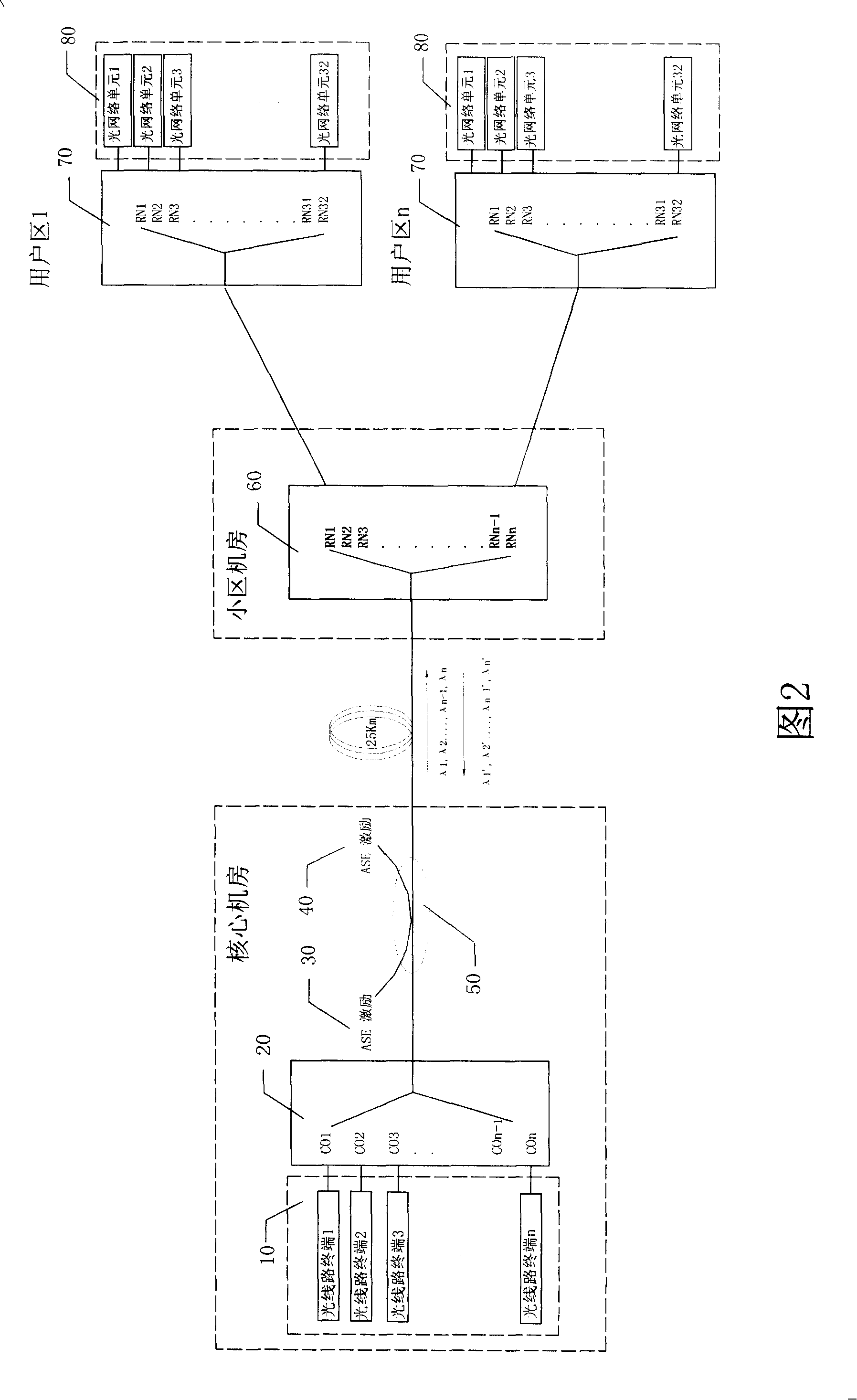
[0032] As shown in Figure 2, a passive optical network system based on wavelength division multiplexing technology includes:

[0033] There are multiple optical line terminals 10, and each optical line terminal adopts mutually independent uplink wavelengths and downlink wavelengths. That is, the optical line terminals 1, 2,..., n respectively use optical signals with wavelengths λ1, λ2,..., λn as upstream optical signals, and the optical network optical line terminals 1, 2,..., n respectively use wavelengths λ1', The optical signals of λ2', ..., λn' are used as downstream optical signals. Each optical line terminal can be connected to a metropolitan area network through an optical fiber interface, or connected to a core switch and other equipment through a connection method such as a 100M or Gigabit Ethernet port;

[0034] The wavelength division multiplexer / demultiplexer 20 optically connected to the plurality of optical line terminals, when the downstream optical signals output ...


PUM


Abstract

A network system of light without light source based on the wavelength division multiplexing technique includes a plurality of optical line terminals which adopt uplink wavelength and downlink wavelength that are mutually independent, a wavelength division multiplexing / demultiplexer connected with the plurality of optical line terminals, a wavelength division multiplexing multiplexer connected with the wavelength division multiplexing / demultiplexer by optical fiber, and a plurality of optical splitters which adopt the same uplink wavelength and the same downlink wavelength corresponding to the optical line terminals and are connected with the wavelength division multiplexing multiplexer. A plurality of optical network units optically connected with the optical splitters. The invention realizes optical fibre communication among a plurality of optical line terminals and a plurality of optical network units through a single optical fibre, thus saving the optical fibre resources for the connecting section between an MAN and a district and reducing the cost of optical fibre access. When the network bandwidth is updating, alteration on the updating of the network bandwidth can be realized only by increasing the qualities of the accessed optical network line terminals and corresponding optical splitters, thus greatly reducing the alteration cost.

Description

Technical field [0001] The invention belongs to the technical field of passive optical networks, and particularly relates to a passive optical network system based on wavelength division multiplexing technology. Background technique [0002] Passive optical network (PON) provides the connection between the optical line terminal (OLT) and multiple optical network units (ONU), and shares the optical fiber medium between the OLT and the remote node (RN). This kind of business is transparent and other advantages, while PON can smoothly transition to fiber to the home (FTTH), so it has bright development prospects. [0003] EPON is a power-splitting passive optical network, which uses star coupler branching, and uses TDMA / TDM for uplink / downlink transmission to achieve shared channel bandwidth. Due to optical power allocation, the number of ONUs is limited and further network expansion is affected. [0004] Traditional EPON can install 1 OLT on each optical fiber to carry 32 users. Al...

Claims


Application Information

Patent Timeline
Patent Type & Authority Applications(China)
IPC IPC(8): H04J14/02
Inventor 高义河陆肖元刘浩锋
Owner SHANGHAI BROADBAND TECH
Why Eureka
Try Eureka