
Power management system with charger and boost controller

A power management system and controller technology, which is applied in current collectors, battery circuit devices, and conversion equipment without intermediate conversion to AC, can solve problems such as excessive power loss, reduced system efficiency, and reduced conversion efficiency.

Inactive Publication Date: 2008-06-18
O2 MICRO INC
View PDF0 Cites 24 Cited by
  • Summary
  • Abstract
  • Description
  • Claims
  • Application Information

AI Technical Summary

Problems solved by technology

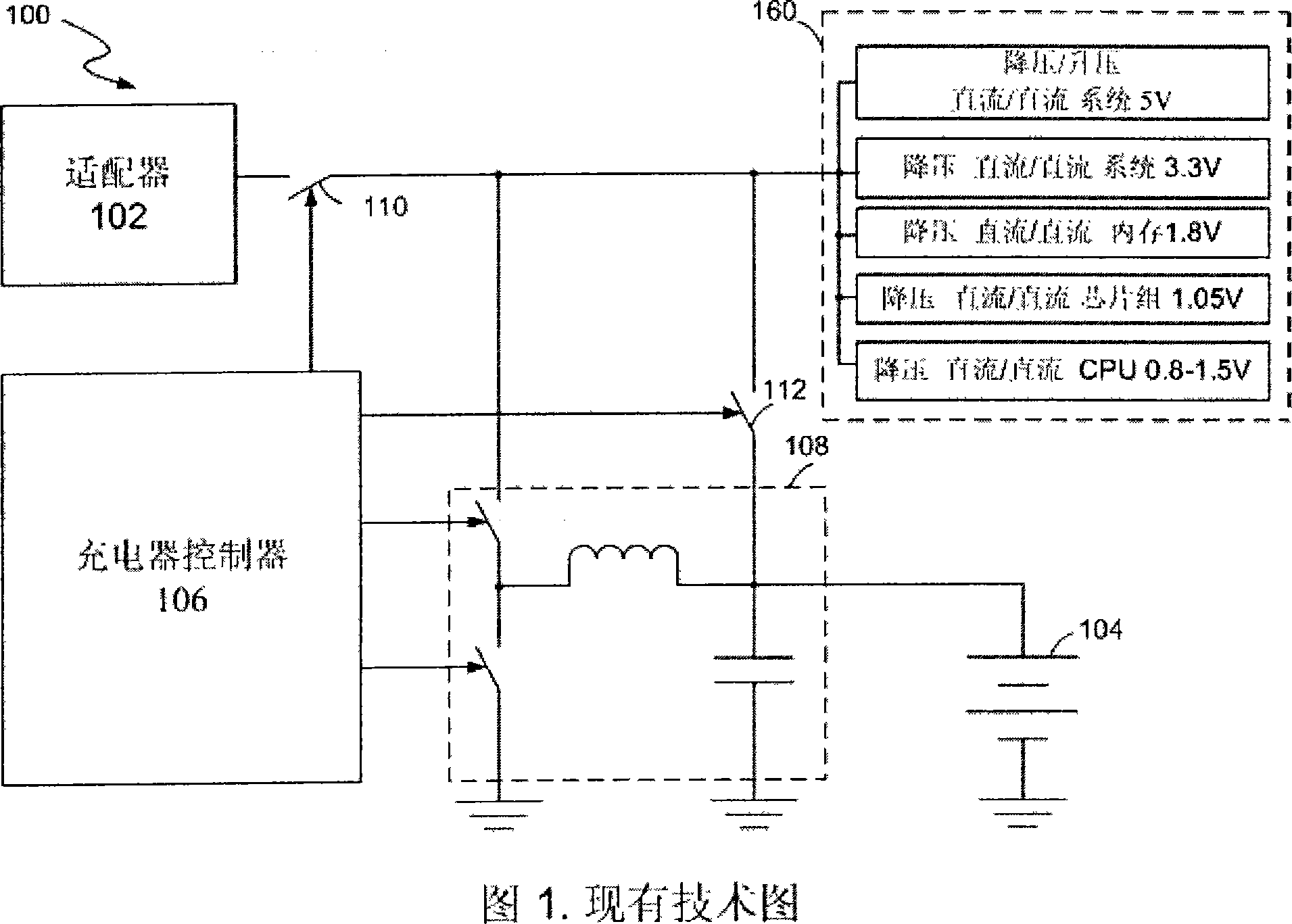
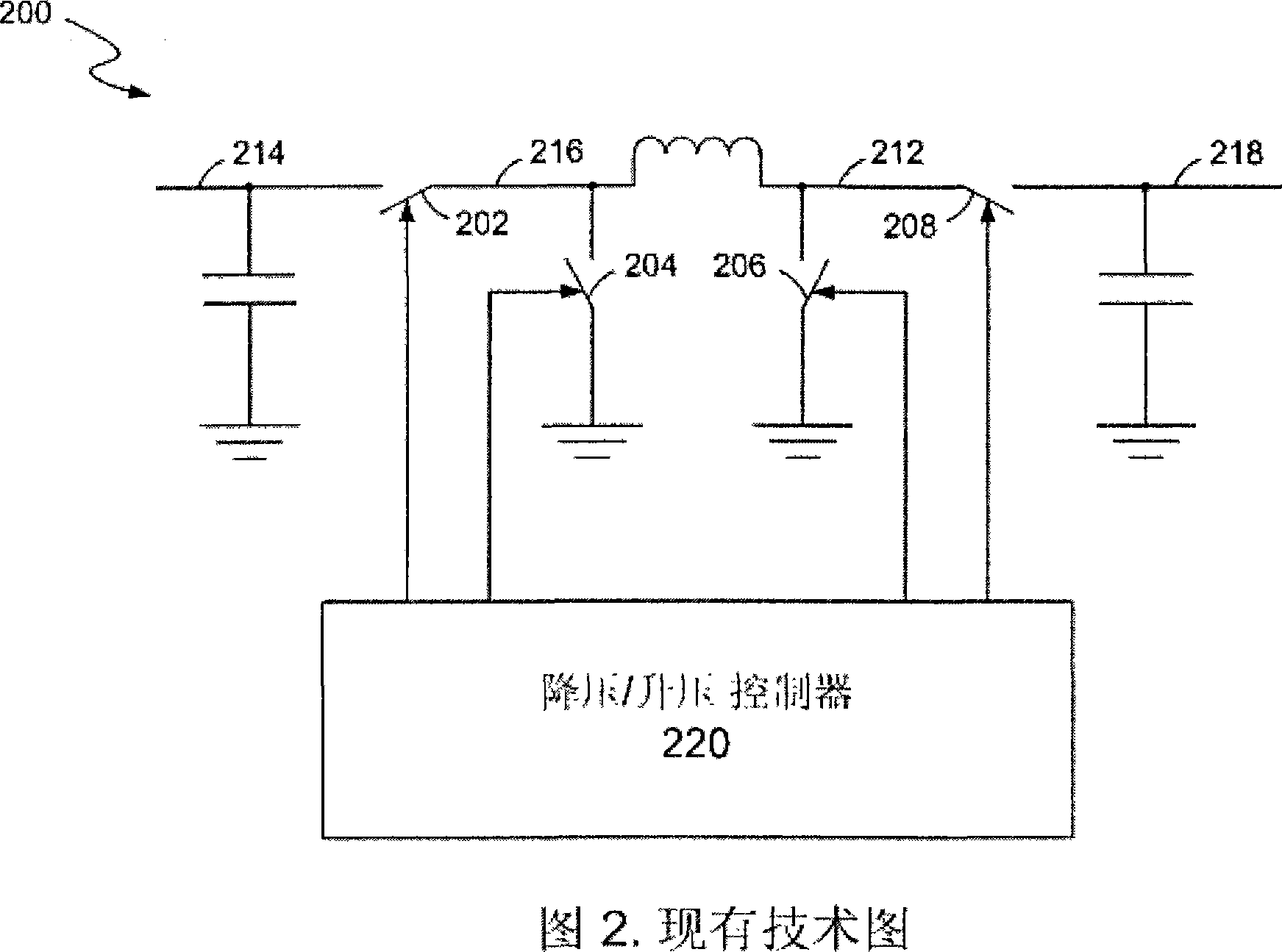
Thus the buck / boost converter 200 requires multiple switches, which increases cost and reduces system efficiency
In addition, when the buck / boost converter 200 is operating in the buck mode, the switch 208 is often turned on, which causes excessive power loss
Similarly, when the buck / boost converter 200 works in the boost mode, the switch 202 is often turned on, which also causes excessive power loss
In addition, in the conversion stage, when the input voltage is almost equal to the output voltage, all the switches 202, 204, 206 and 208 will be in the active state, which also reduces the overall conversion efficiency

Method used


Image

  • Power management system with charger and boost controller
  • Power management system with charger and boost controller
  • Power management system with charger and boost controller

Examples


Embodiment Construction

[0018] Detailed reference will be given below to examples of the present invention. While the invention will be described in conjunction with examples, it will be understood that it is not intended to limit the invention to these examples. On the contrary, the invention is intended to cover various alternatives, modifications and equivalents as defined within the spirit and scope of the invention as defined by the appended claims.

[0019] Furthermore, in the following detailed description of the invention, numerous specific details are set forth in order to provide a thorough understanding of the invention. However, it will be understood by those skilled in the art that the present invention may be practiced without these specific details. In other instances, well-known schemes, procedures, components and circuits have not been described in detail so as not to obscure the gist of the present invention.

[0020] In one embodiment, the present invention provides a power manag...


PUM


Abstract

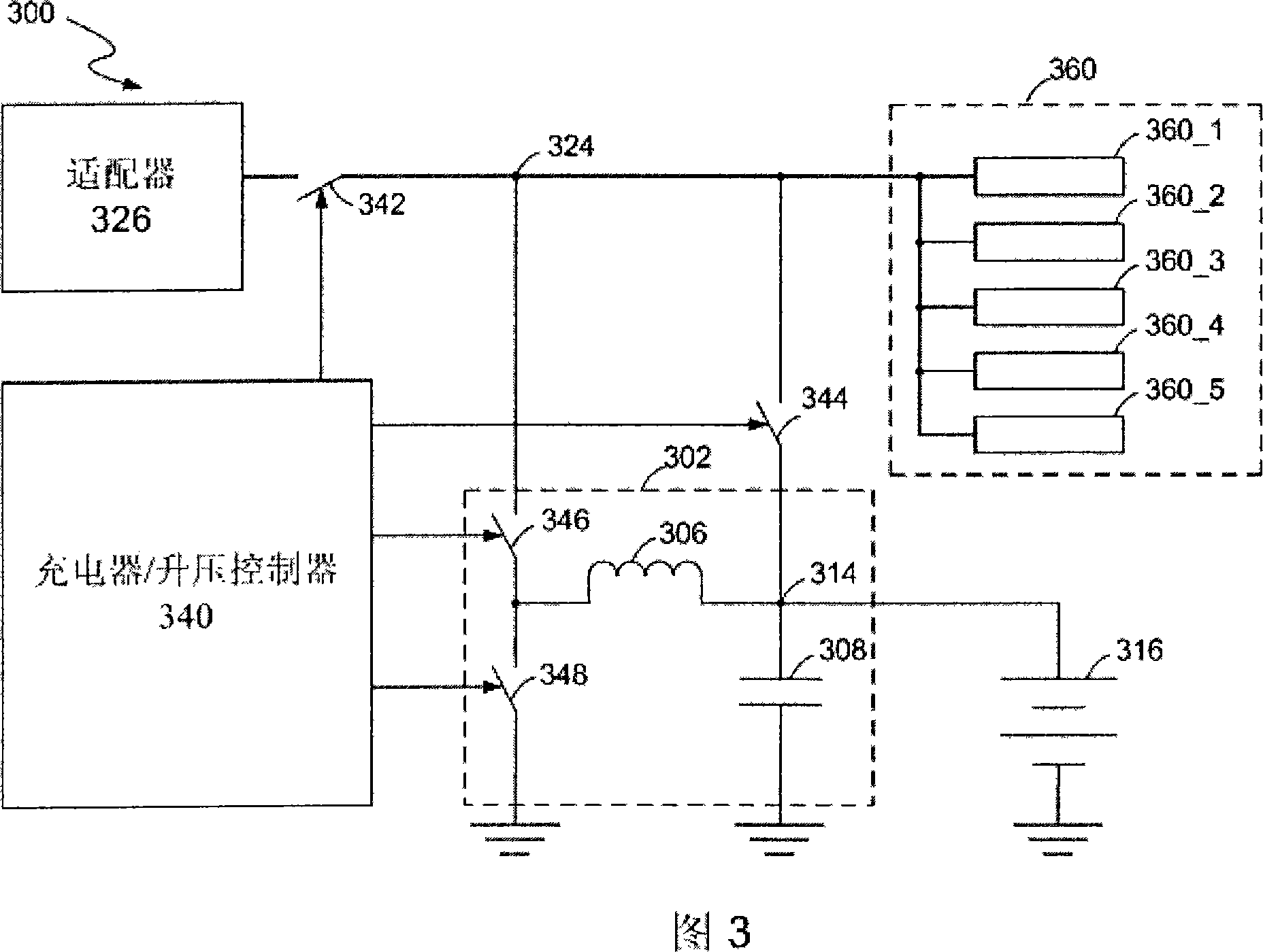
A power management system comprises a power conversion stage and a controller. The power conversion stage has two terminals. The first terminal is coupled to a first power source which provides a first voltage. The second terminal is selectively coupled to a second power source which provides a second voltage. The controller coupled to the power conversion stage can select a mode from at least a first mode and a second mode. In the first mode, the power conversion stage receives the first voltage at the first terminal and generates a step-up voltage at the second terminal. The generated step-up voltage is greater than the first voltage. In the second mode, the power conversion stage receives the second voltage at the second terminal and generates a step-down voltage at the first terminal for charging the first power source. The generated step-down voltage is less than the second voltage.

Description

[0001] Related Patent Applications [0002] This application claims priority to US Provisional Application No. 60 / 856,075, filed November 1, 2006, which is hereby incorporated by reference in its entirety. technical field [0003] The present invention relates to power management systems, and more particularly to power management systems with charger / boost controllers. Background technique [0004] Today, lithium-ion battery cell technology is gradually involving high power density battery cells. However, these high power density cells have the characteristic that the minimum discharged cell voltage is reduced (eg, to 2.2V). For example, since the battery voltage of a Li-ion battery with 2 cells (2-cell Li-ion battery) can range from 4.4V to 8.8V, a portable device powered by a 2-cell Li-ion The process of cell lithium-ion battery's 5V output voltage faces challenges. Therefore, in order to reliably generate a 5V output voltage, a new buck-boost converter is required to r...

Claims


Application Information

Patent Timeline
Patent Type & Authority Applications(China)
IPC IPC(8): H02J7/00H02M3/04H02M3/10
Inventor 拉兹洛·利普赛依
Owner O2 MICRO INC
Learn More