
Liquid crystal panel and liquid crystal display device

A liquid crystal panel and substrate technology, applied in static indicators, nonlinear optics, instruments, etc., can solve problems such as poor color display effect of liquid crystal panel, and achieve the effect of improving color display effect and sensitivity balance

Inactive Publication Date: 2008-06-18
INNOCOM TECH SHENZHEN +1
View PDF0 Cites 2 Cited by
  • Summary
  • Abstract
  • Description
  • Claims
  • Application Information

AI Technical Summary

Problems solved by technology

[0007] In order to solve the problem of poor color display effect of the prior art liquid crystal panel, it is necessary to provide a liquid crystal panel with better color display effect.

Method used


Image

  • Liquid crystal panel and liquid crystal display device
  • Liquid crystal panel and liquid crystal display device
  • Liquid crystal panel and liquid crystal display device

Examples


Embodiment Construction

[0018] Please refer to FIG. 4 , which is a schematic structural diagram of a preferred embodiment of the liquid crystal display device of the present invention. The liquid crystal display device 2 includes a liquid crystal panel 20 and a backlight module 22 . The liquid crystal panel 20 includes a first substrate 24 , a second substrate 26 corresponding to the first substrate 24 , and a liquid crystal layer 25 filled between the two substrates 24 and 26 . The backlight module 22 is disposed adjacent to the first substrate 24 .

[0019] Please also refer to FIG. 5 , which is a partial plan view of the first substrate 24 . The first substrate 24 includes a first base 241, a plurality of scan lines 242 arranged parallel to each other on the first base 241, a plurality of data lines 243 parallel to each other and insulated and perpendicular to the scan lines 242, and a plurality of data lines 243 located on the first base 242. The thin film transistor 246 at the intersection of ...


PUM


Abstract

The invention relates to a liquid crystal panel and a liquid crystal display device. The liquid crystal panel comprises a first substrate and a second substrate corresponding to the first substrate; the second substrate comprises a colorful filter layer and the colorful filter layer comprises a colored layer, moreover, the colored layer is provided with a red colored unit, a green colored unit and a blue colored unit; the red colored unit, the green colored unit and the blue colored unit are bar structure with different width and the width of the red colored unit and the green colored unit is directly proportional to the red wavelength and the green wavelength adopted; the width of the green colored unit and the blue colored unit is in reverse proportion to the green wavelength and the blue wavelength.

Description

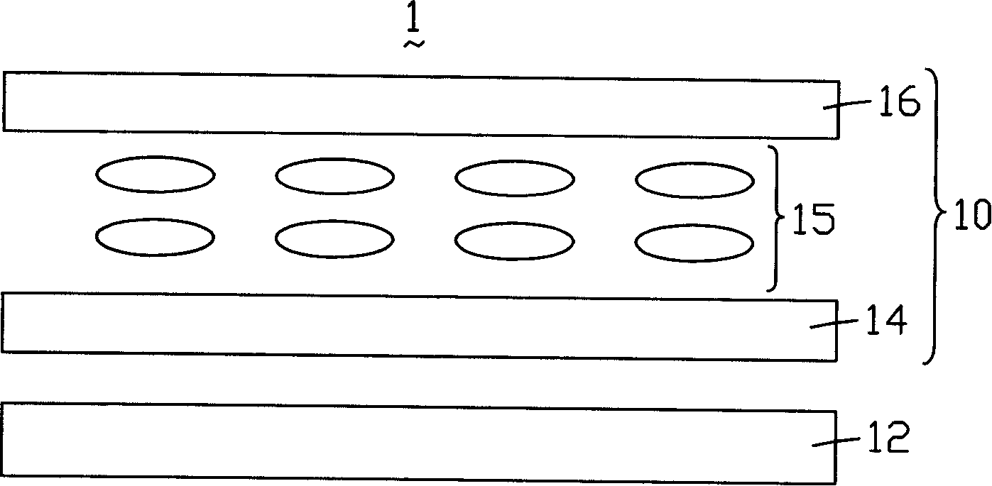
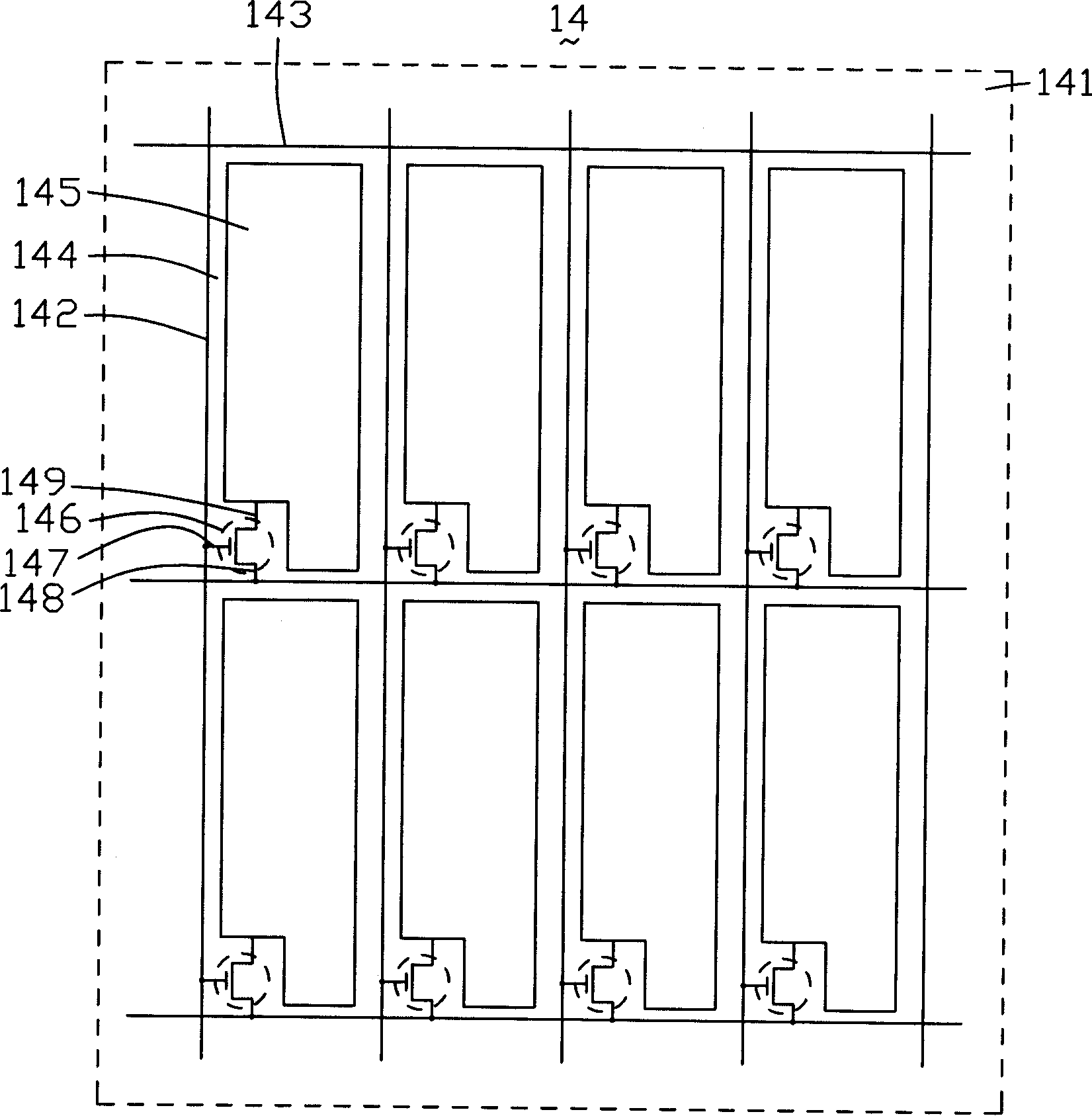
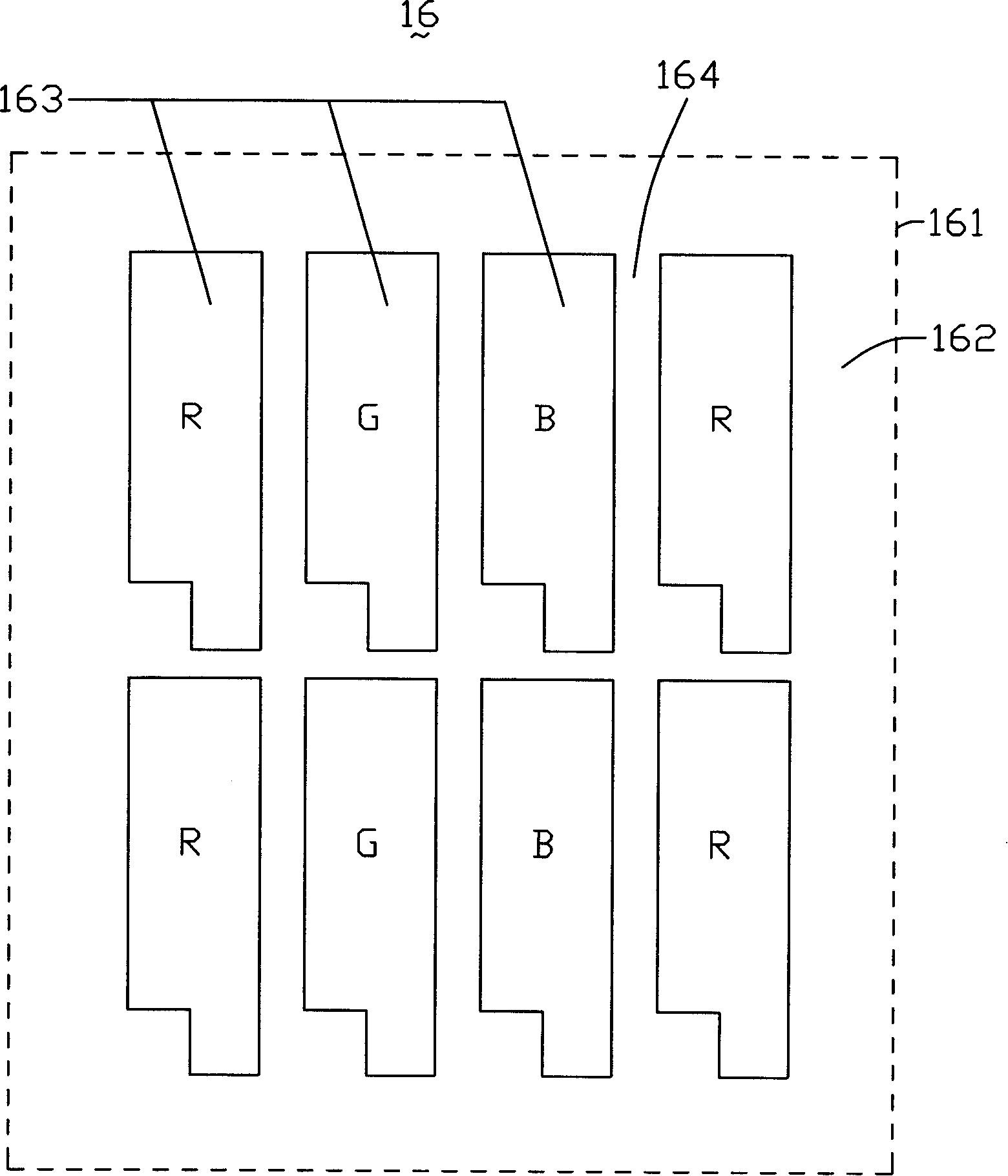
technical field [0001] The invention relates to a liquid crystal panel and a liquid crystal display device. Background technique [0002] Liquid crystal display devices are widely used because of their low radiation, light, thin and small size, and low power consumption. [0003] see figure 1 , is a structural schematic diagram of a prior art liquid crystal display device. The liquid crystal display device 1 includes a liquid crystal panel 10 and a backlight module 12 . The liquid crystal panel 10 includes a first substrate 14 , a second substrate 16 corresponding to the first substrate 14 , and a liquid crystal layer 15 filled between the two substrates 14 and 16 . The backlight module 12 is disposed adjacent to the first substrate 14 . [0004] Please also refer to figure 2 , is a partial plan view of the first substrate 14 . The first substrate 14 includes a first base 141, a plurality of scanning lines 142 arranged parallel to each other on the first base 141, a p...

Claims


Application Information

Patent Timeline
IPC IPC(8): G02F1/1335G02F1/1362G02F1/133
Inventor 王华斌
Owner INNOCOM TECH SHENZHEN
Learn More