Camera lens system, imaging device and electronic device
A camera lens, lens technology, applied in optical components, instruments, optics, etc., can solve problems such as difficult volume or balance of viewing angles
- Summary
- Abstract
- Description
- Claims
- Application Information
AI Technical Summary
Problems solved by technology
Method used
Image

Examples
no. 1 example 》
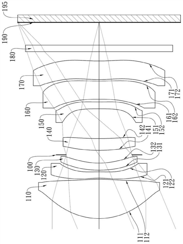
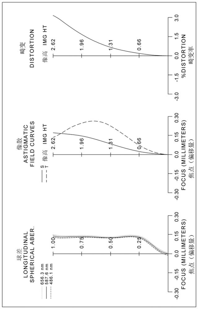
[0179] Please refer to the first embodiment of the present invention Figure 1A , for the aberration curve of the first embodiment, please refer to Figure 1B . The imaging device of the first embodiment includes an imaging lens system (not otherwise labeled) and an electronic photosensitive element 195. The imaging lens system includes a first lens 110, a second lens 120, a third lens 130, The aperture 100, the fourth lens 140, the fifth lens 150, the sixth lens 160, the seventh lens 170 and the imaging surface 190, and the electronic photosensitive element 195 is arranged on the imaging surface 190 of the imaging lens system, wherein the imaging lens includes seven lenses ( 110, 120, 130, 140, 150, 160, 170), there are no other interpolated lenses among the seven lenses.
[0180] The first lens 110 has a positive refractive power and is made of plastic. The object side 111 is convex at the near optical axis, and the image side 112 is convex at the near optical axis. Both th...
no. 2 example 》
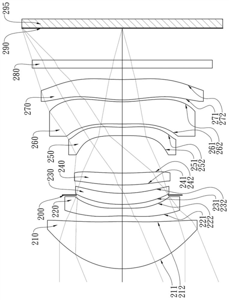
[0238] Please refer to the second embodiment of the present invention Figure 2A , for the aberration curve of the second embodiment, please refer to Figure 2B . The imaging device of the second embodiment includes an imaging lens system (not otherwise labeled) and an electronic photosensitive element 295. The imaging lens system includes a first lens 210, a second lens 220, an aperture 200, a third lens 210 from the object side to the image side in sequence. Lens 230, the fourth lens 240, the fifth lens 250, the sixth lens 260, the seventh lens 270 and the imaging surface 290, and the electronic photosensitive element 295 is arranged on the imaging surface 290 of the imaging lens system, wherein the imaging lens includes seven lenses ( 210, 220, 230, 240, 250, 260, 270), there are no other interpolated lenses among the seven lenses.
[0239] The first lens 210 has a positive refractive power and is made of plastic. The object side 211 is convex at the near optical axis, an...
no. 3 example 》
[0254] Please refer to the third embodiment of the present invention Figure 3A , for the aberration curve of the third embodiment, please refer to Figure 3B . The imaging device of the third embodiment includes an imaging lens system (not otherwise labeled) and an electronic photosensitive element 395. The imaging lens system includes a first lens 310, a second lens 320, a diaphragm 300, a third lens in sequence from the object side to the image side. Lens 330, the fourth lens 340, the fifth lens 350, the sixth lens 360, the seventh lens 370 and the imaging surface 390, the electronic photosensitive element 395 is arranged on the imaging surface 390, wherein the imaging lens comprises seven lenses (310, 320, 330, 340, 350, 360, 370), there are no other interpolated lenses among the seven lenses.
[0255] The first lens 310 has a positive refractive power and is made of plastic. The object side 311 is convex at the near optical axis, and the image side 312 is convex at the ...
PUM
 Abstract
Description
Claims
Application Information
 - Generate Ideas
- Intellectual Property
- Life Sciences
- Materials
- Tech Scout
- Unparalleled Data Quality
- Higher Quality Content
- 60% Fewer Hallucinations
Browse by: Latest US Patents, China's latest patents, Technical Efficacy Thesaurus, Application Domain, Technology Topic, Popular Technical Reports.
© 2025 PatSnap. All rights reserved.Legal|Privacy policy|Modern Slavery Act Transparency Statement|Sitemap|About US| Contact US: help@patsnap.com