
Gap-change sensing through capacitive techniques

A capacitance change, capacitance technology, applied in electromagnetic measurement devices, electric/magnetic solid deformation measurement, circuits, etc., can solve problems such as increased cost and increased complexity

Inactive Publication Date: 2008-06-11
LOADSTAR SENSORS INC
View PDF0 Cites 6 Cited by
  • Summary
  • Abstract
  • Description
  • Claims
  • Application Information

AI Technical Summary

Problems solved by technology

These operations can add complexity, which can provide only 60% productivity, and can make the specific design of the load cell only usable for a limited measurement range (eg, between 10-5,000 psi)
Also, the limitations of the Wheatstone bridge structure may only allow a limited number of form factors (e.g., S-shaped form factors and / or single-point form factors, etc.) to obtain the desired load cell characteristics
For many industrial applications, the complexity of the various operations involved in making and using the load cell can drive up the cost (e.g., hundreds and thousands of dollars)

Method used


Image

  • Gap-change sensing through capacitive techniques
  • Gap-change sensing through capacitive techniques
  • Gap-change sensing through capacitive techniques

Examples


no. 1 example

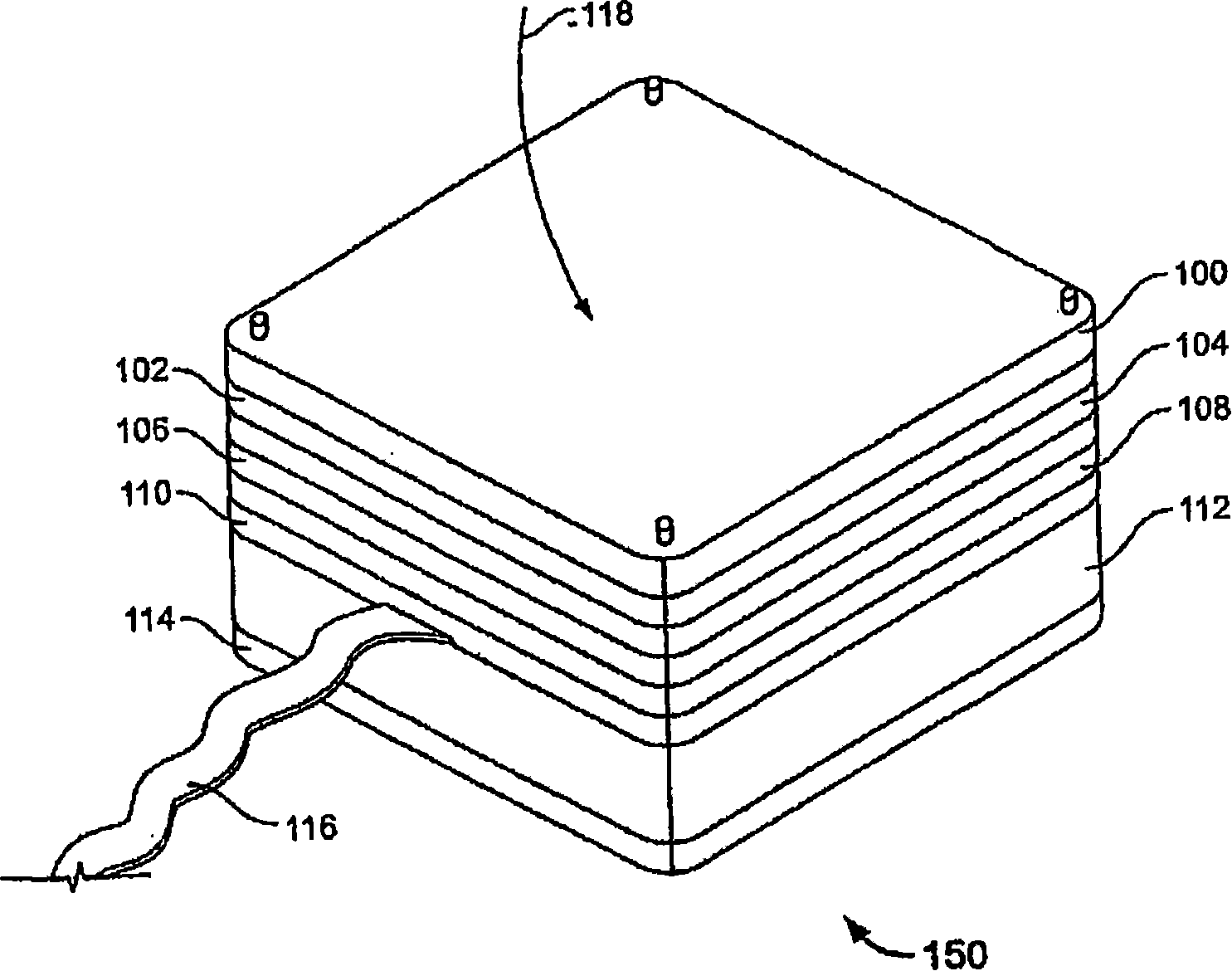
[0040] Figure 6 is according to one embodiment figure 1 A network startup diagram of device 150 is shown. In the first embodiment, the device 150A is connected via an interface cable (eg, figure 1 cable 116 and / or cable 616 of FIG. 6 ) to data processing system 602. The second device 150B is wirelessly connected to the data processing system 602 through the network 600 . In one embodiment, network 600 is the Internet. In another embodiment, the network 600 is a local area network. Data processing system 606 may receive data from device 150A and / or device 150B via network 600 (eg, output data measuring forces and / or loads, etc.). In one embodiment, data processing system 606 analyzes data (eg, measurements) generated by various operations of a device (eg, stacked device 150A). Access device 604 (eg, a device capable of wireless communication between devices forming a wireless network) may provide a wireless connection to device 150B. In one embodiment, device 150B include...


PUM


Abstract

A gap-change sensing through capacitive techniques is disclosed. In one embodiment, an apparatus includes a first conductive surface and a second conductive surface substantially parallel to the first conductive surface, and a sensor to generate a measurement based on a change in a distance between the first conductive surface and the second conductive surface. The change in the distance may be caused by a deflection of the first conductive surface with respect to the second conductive surface, and the deflection may be a compressive force and / or an expansive force. The sensor may apply an algorithm that converts a change in capacitance to at least one of a change in voltage and / or a change in frequency to generate the measurement. The change in the distance may be caused by a load applied to the surface above the first conductive surface with respect to the second conductive surface.

Description

technical field [0001] The present disclosure relates generally to the technical field of measurement devices and, in one embodiment, to sensing gap changes by capacitive techniques. Background technique [0002] A load cell may be a device (eg, a transducer) that converts force into a differential signal (eg, a differential electrical signal). Load cells may be used in a variety of industrial applications (eg, dials, truck weighing stations, tension measurement systems, force measurement systems, load measurement systems, etc.). Load cells can be made by using strain gauges. Strain gauges can be used to measure deformation (eg, strain) of an object. The strain gauge may include a flexible pad supporting a metal foil pattern etched on the flexible pad. As the object deforms, so does the foil pattern, causing its electrical resistance to change. [0003] Strain gauges can be connected to other strain gauges to form a load cell in a Wheatstone bridge configuration (e.g. co...

Claims


Application Information

Patent Timeline
Patent Type & Authority Applications(China)
IPC IPC(8): H01L23/34
CPCG01B7/22G01L1/142G01G7/06G01G23/3735H01L23/34
Inventor 威廉·D·达伦巴赫迪夫亚西姆哈·哈里什
Owner LOADSTAR SENSORS INC
Learn More