Friction clutch

A technology of friction clutches and disc springs, applied in the direction of friction clutches, clutches, mechanically driven clutches, etc.

Inactive Publication Date: 2013-06-05
SCHAEFFLER TECH AG & CO KG
View PDF2 Cites 0 Cited by
  • Summary
  • Abstract
  • Description
  • Claims
  • Application Information

AI Technical Summary

Problems solved by technology

[0003] In the known state of the art, however, there is a relatively high frictional hysteresis in the region of the pivoting bearing of the disc spring-like component on the housing, so that in such friction clutches the engagement force curve differs from the disengagement force curve. significantly

Method used


Image

  • Friction clutch
  • Friction clutch
  • Friction clutch

Examples


Embodiment Construction

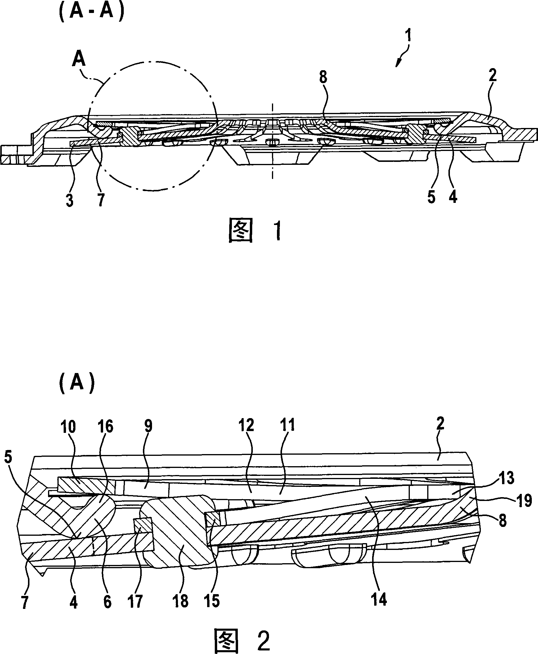
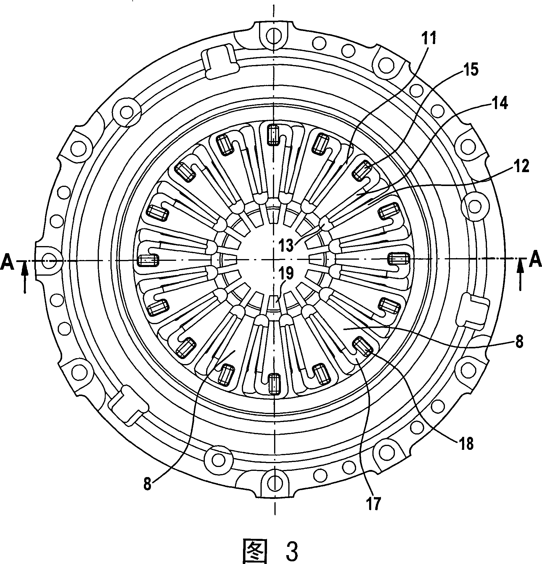
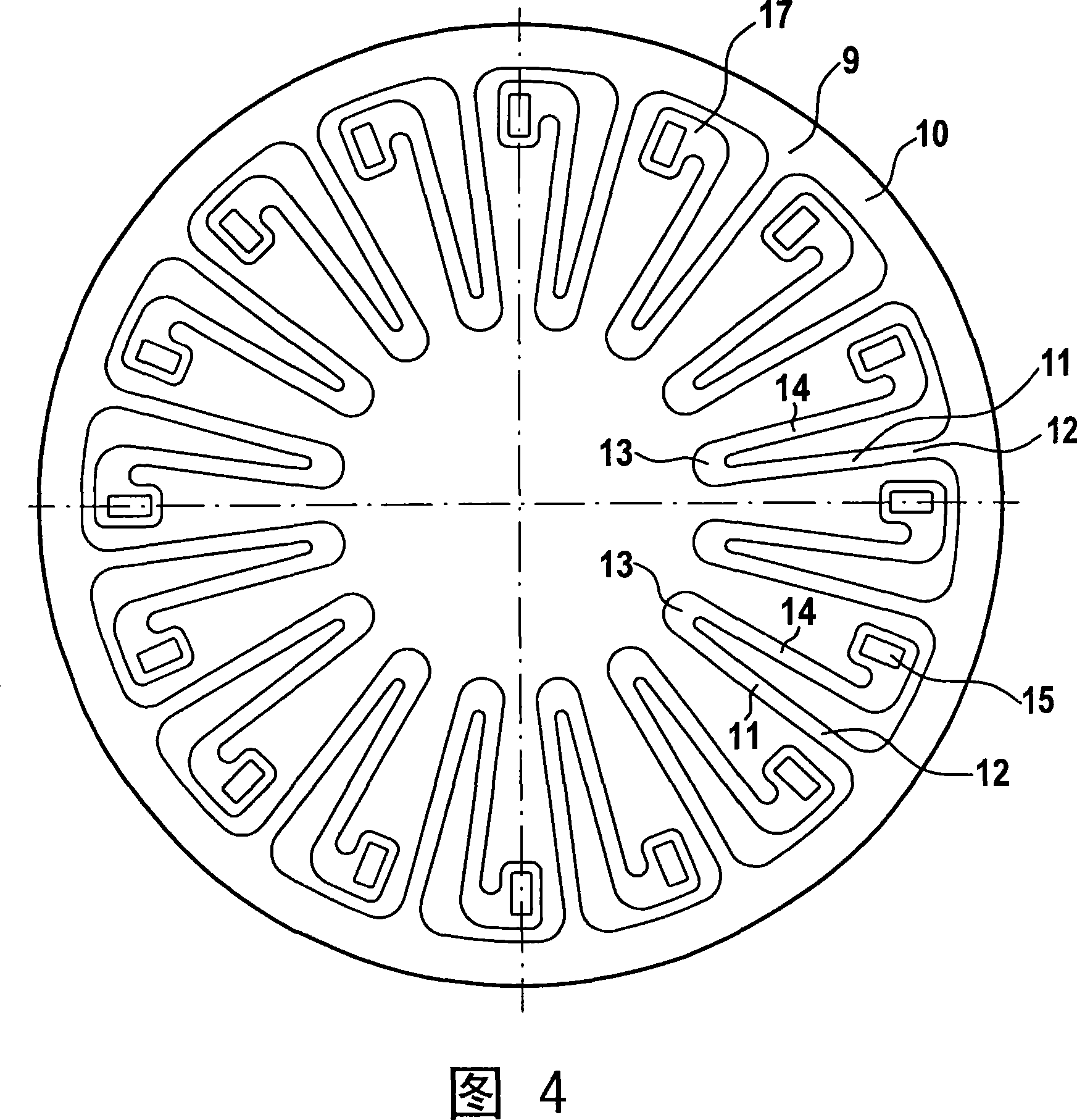
[0018] The friction clutch 1 shown in these figures has a housing 2 here made of sheet metal and a pressure plate which is non-rotatably connected to the housing but displaceable in a limited axial direction. The disk is not shown here. Axially clamped between the pressure plate and the cover 2 is a compression disc spring 4, which can be obtained, for example, from figure 2 As can be seen in , it can be swiveled like a double-armed lever at the radial height of the annular support region 5 arranged on the cover side. The disk spring 4 acts on a pressure plate with a radially far outer region 3 . The pressure plate is non-rotatably connected to the housing 2 via leaf springs directed in the circumferential direction or tangentially. The friction clutch 1 can be mounted on a counter-pressure plate, not shown here, wherein a frictional contact between the friction surface of the counter-pressure plate and the friction surface of the pressure plate can be carried out in a know...


PUM


Abstract

Friction coupling comprises spring arrangements formed by an annular spring (9) having an annular base body (10) axially supported by a housing (2). Elastically deformable longitudinal brackets (11) run from the housing and are axially connected to a component (4) formed as a disk spring. Preferred Features: The base body is formed as a disk spring. The longitudinal brackets are clamped in the axial direction between the housing and the component. The base body and the longitudinal brackets are formed as one piece.

Description

technical field [0001] The invention relates to a friction clutch, in particular for a motor vehicle, which has a pressure plate which is non-rotatably connected but displaceably axially limited to a housing, In this case, a disc spring-like component is arranged between the housing and the pressure plate, which is supported on the one hand on an annular pivot area arranged on the housing and on the other hand for The pressure plate is loaded in the direction of the friction lining of the clutch disc, and the disk spring-like component is also subjected to a blocking force generated by spring means in the direction of the pivoting region in the axial direction. It is carried by the disc spring-like component and is supported with pretension on the housing. Background technique [0002] Such clutches are known, for example, from US 4,210,233 and DE 34 33 644 C2. [0003] In the known state of the art, however, there is a relatively high frictional hysteresis in the region o...

Claims


Application Information

Patent Timeline
Patent Type & Authority Patents(China)
IPC IPC(8): F16D13/71
CPCF16D13/585F16D13/583
Inventor T·林登鲍姆M·奥特曼R·迈因哈德O·弗里德曼
Owner SCHAEFFLER TECH AG & CO KG
Why Eureka
Try Eureka