
Laser lancet

A scalpel and laser technology, applied in the fields of biology and medicine, can solve the problems of not easy to make small size, not easy to miniaturize, and unpredictable practicability.

Inactive Publication Date: 2008-06-11
WYSELIFE TECH LTD SHENZHEN
View PDF2 Cites 8 Cited by
  • Summary
  • Abstract
  • Description
  • Claims
  • Application Information

AI Technical Summary

Problems solved by technology

[0007] 2) So far, no laser scalpel product has been found that can change the parameters of the lateral or front and rear lateral emission beams
Although individual patents, such as EP 0 372 362 A2, involve changing the focal length of the beam, that is, the purpose of changing the focal length of the beam is achieved by drawing the optical fiber into a conical shape, or adding a spherical lens at the end of the optical fiber, or making the end of the optical fiber into a spherical lens, etc. However, its structure is only suitable for axisymmetric beam distribution of axial emission (the beam cross section perpendicular to the central axis of the fiber is point-like or spot-like), not for lateral emission and non-axisymmetric beam distribution (the beam cross section perpendicular to the fiber axis is in the shape of linear or elliptical spot) beam
There are also individual patents, such as US 5,366,456, which involve changing the focal length of the front or rear side beams, that is, changing the focal length of the emitted beam by adding a specific spherically symmetrical mirror directly in front of the fiber, but its effect is mainly along the axis of the fiber The axis of the center, not the side perpendicular to the axis, and the reflective mirror used is spherical, which can only transform the divergence or focal length of the wave surface that is symmetrical about the central axis of the optical fiber, and cannot be transformed into other shapes, such as Non-axisymmetric linear or elliptical cylindrical beams parallel to the fiber axis or at a certain angle
[0008] 3) The optical surface of the laser surgical head in the prior art is susceptible to different degrees of contact pollution and thermal damage to the head associated with contact pollution
However, due to the complex structure of the cutter head involved in this patent, it is not easy to make it into a tiny size that can meet endoscopic surgery
[0009] 4) The heat dissipation technology of the existing cutter head has different degrees of hidden dangers of thermal damage to the cutter head
In addition to the above-mentioned pollution of the optical surface of the mirror, if the heat generated by the surgical operation itself such as vaporization is not properly dissipated, it is enough to cause a sudden change in the temperature of the entire cutter head, and the huge stress generated can lead to deformation of the cutter head, bursting of parts, and degumming etc., which can eventually lead to the failure of the cutter head, and even cause accidents
Although some patents, such as US 5,366,456, even design heat dissipation channels with variable apertures, due to the complex overall structure of the cutter head, it is not easy to miniaturize, and the practicability of this structure for endoscopic surgical head heat dissipation is difficult to predict

Method used


Image

  • Laser lancet
  • Laser lancet
  • Laser lancet

Examples


Embodiment Construction

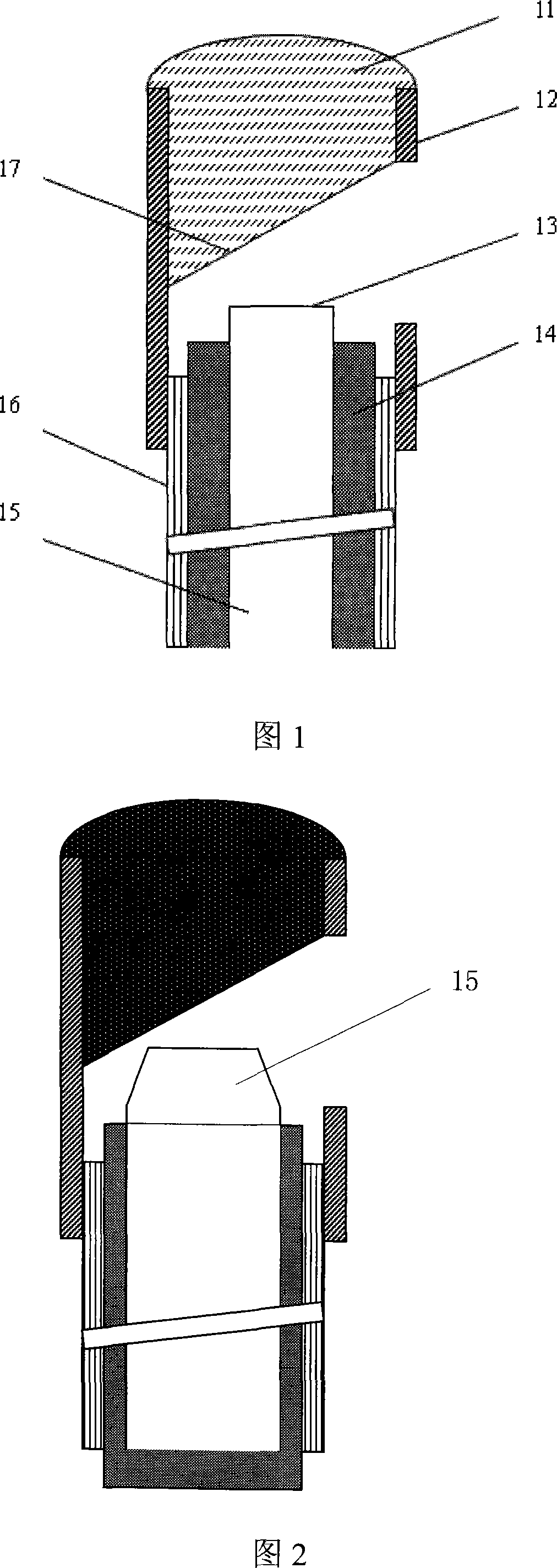
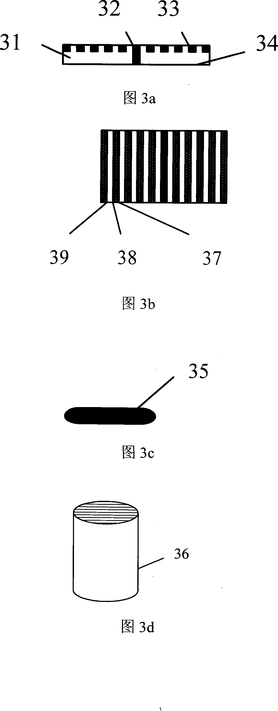
[0027] The laser scalpel of the present invention comprises a cutter head, and Fig. 1 is a cutter head optics overall structural diagram of the laser scalpel of the present invention, and this cutter head comprises a support structure 11, a cutter head main body 12, a focusing shaping device 13, and an optical cable inner layer wrapping material 14, energy transmission optical fiber 15, optical cable outer protective sheath 16 and beam emission angle control unit 17. The energy transmission optical fiber 15 includes an emitting end face. The beam emission angle control unit 17 includes an optical fiber pigtail that processes the core and cladding into a certain angle and diameter distribution along the axial direction, a pigtail emission end face and a reflective mirror, and the pigtail emission end face, reflection surface Optical or metal thin films with three-dimensional micro-nano structures are arranged on the surface of the mirror. The reflective mirror is set opposite ...


PUM


Abstract

The invention provides a laser scalpel, comprising a scalpel head which comprises a scalpel head body, energy transmission optical fiber and a light-beam emission angle control unit. The scalpel head body is used to support the energy transmission optical fiber and the light-beam emission angle control unit, wherein the energy transmission optical fiber comprises an emitting end face, and the light-beam emission angle control unit comprises tail optical fiber, a tail optical fiber emission end face and a reflecting face mirror. The reflecting face mirror and the emission end face are arranged relatively to form a certain angle, and a three dimensional micro-nano structure is arranged on at least one of the surfaces of the reflecting face mirror or tail optical fiber emission end face.

Description

technical field [0001] The invention relates to the fields of medicine and biology, in particular to a laser scalpel used in the fields of medicine and biology. Background technique [0002] Laser light waves irradiating biological tissues can produce effects such as photoshedding, photocoagulation and photovaporization, and related principles have been used to make laser scalpels with different functions. Because laser surgery has many advantages that traditional surgery cannot achieve at present, the demand for laser scalpels is increasing day by day, and the functional varieties are becoming more and more specialized. Since various surgeries, especially various endoscopic surgeries require laser scalpel heads with different specific functions, many new laser scalpel technologies have been invented and created. [0003] In actual operation, the laser and the scalpel head are generally used in a separate working mode, and different surgical needs are met through the cooper...

Claims


Application Information

Patent Timeline
Patent Type & Authority Applications(China)
IPC IPC(8): A61B18/22
Inventor 马君显
Owner WYSELIFE TECH LTD SHENZHEN
Learn More