Eureka AIR delivers breakthrough ideas for toughest innovation challenges, trusted by R&D personnel around the world.

Two-piece side and floor panel arrangement for box assembly

A technology for carriages and floors, applied to the upper structure of trucks, vehicle components, upper structures, etc., can solve complex and expensive processing tools and other problems, and achieve the reduction of material consumption and cost, simplification of assembly operations, and reduction of total weight Effect

Inactive Publication Date: 2008-06-04
PULLMAN IND
View PDF2 Cites 11 Cited by
  • Summary
  • Abstract
  • Description
  • Claims
  • Application Information

AI Technical Summary

Problems solved by technology

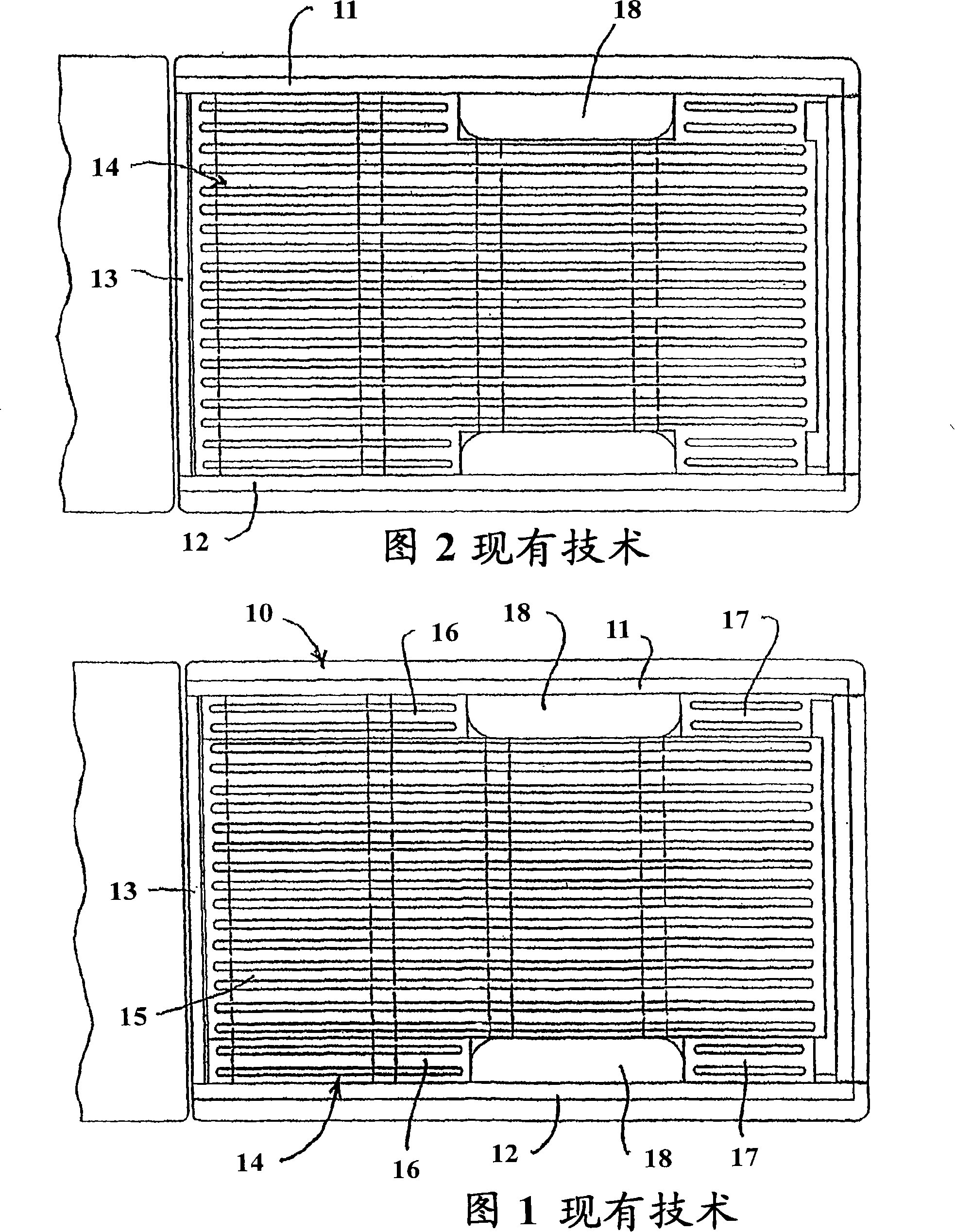
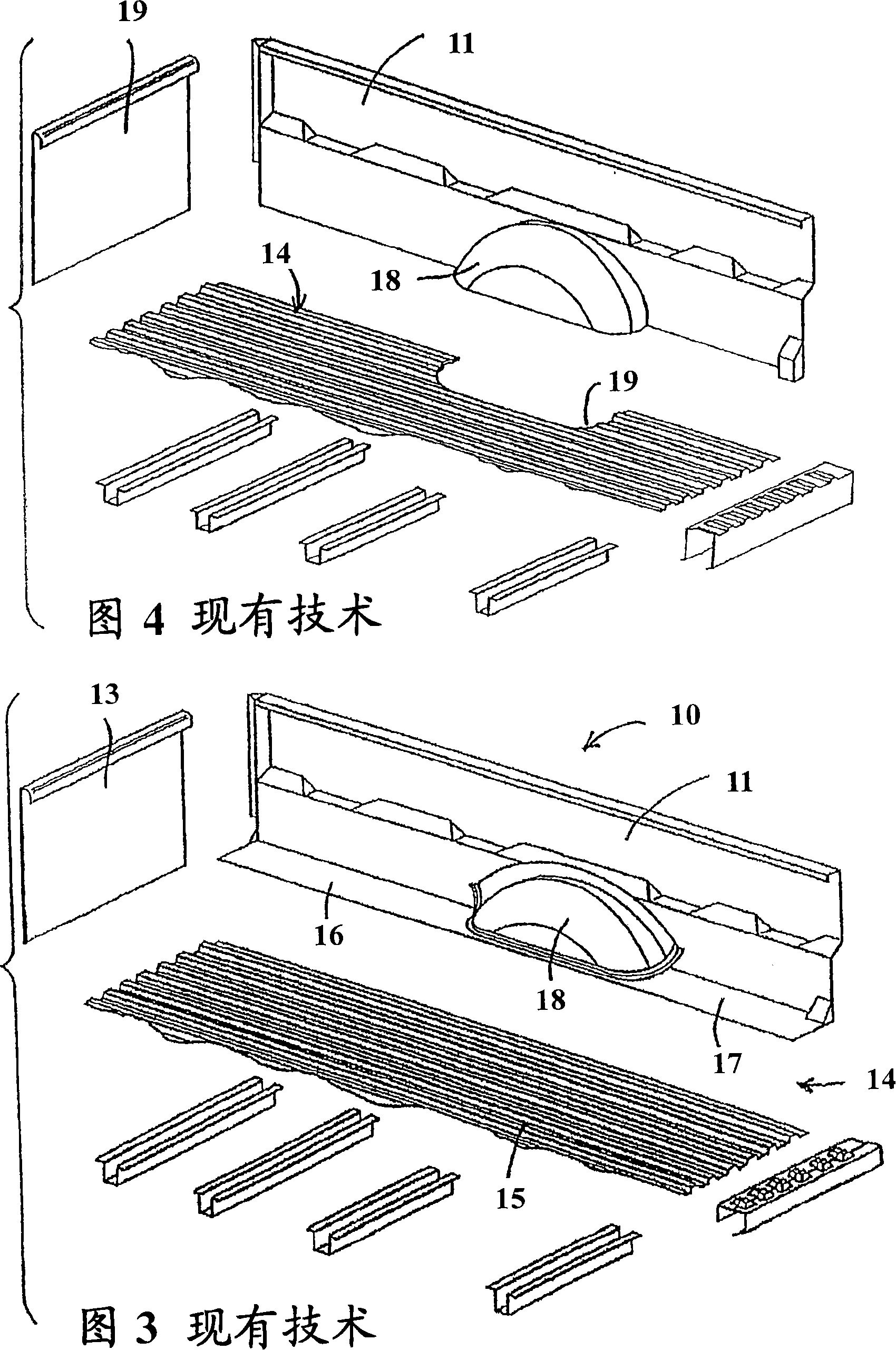
This stamping requires complex and expensive tooling due to its size and complex three-dimensional shape

Method used


Image

  • Two-piece side and floor panel arrangement for box assembly
  • Two-piece side and floor panel arrangement for box assembly
  • Two-piece side and floor panel arrangement for box assembly

Examples


Embodiment Construction

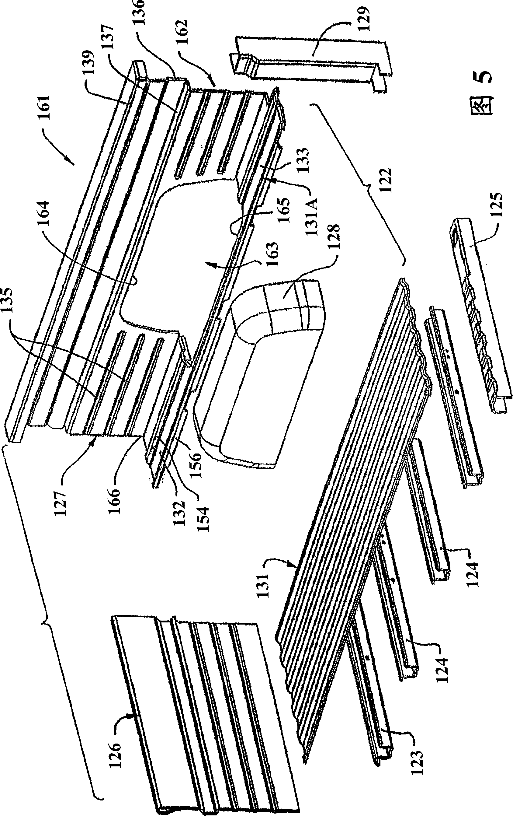
[0032] Referring to Figure 5, there is shown one embodiment of an improved automobile bed assembly 161, particularly a light truck bed assembly, wherein a roll formed quarter Plate 162 (ie, a one-piece bottom / side plate). Only the bottom / side panel 162 on the right is shown in FIG. / Mirror image of the side panel.

[0033] The bed assembly 161 includes a floor (also referred to as a floor) 122 supported on an underlying plurality of beams, such as a front beam 123 , a number of intermediate beams 124 , and a rear beam 125 . An upstanding front panel 126 protrudes upwardly near the front edge of the bottom panel 122, side panels 127 protrude upwardly near each side of the bottom panel, and a wheel well housing 128 is fitted on each side panel 127 and the corresponding side of the bottom panel 122 between the side parts. The rear edges of the side panels engage uprights or struts 129 .

[0034] In the carriage assembly 161, the floor 122 is made up of a plurality of floor s...


PUM


Abstract

A vehicle box assembly (210) having a horizontal floor (211), and upright side panels (211) adjacent opposite side edges of the floor. The floor (211) and side panels (212) are defined by two similar L-shaped members each defining one of the side panels (212) and each defining a floor section (216) integrally and monolithically joined to the respective side panel (217) and extending generally perpendicularly therefrom. The floor sections (216) of the two panel members have lengthwise-extending edge flanges (224) which are joined together in the lengthwise extent of the floor. The panel members are preferably roll-formed so that the floor section has a transversely protruding reinforcing rib (221) extending lengthwise thereof, and the side panel has a channel-like edge rail extending lengthwise along the free edge thereof. The panel members each have a wheel well opening (228) formed therein. The panel members are transversely bent along a lengthwise region to define the L-shape.

Description

technical field [0001] This invention relates to box assemblies for automobiles, such as light trucks, and more particularly to automotive box assemblies utilizing roll-formed panels, and improved methods of making such panels. Background technique [0002] For many years, upwardly opening bed assemblies of automobiles, such as light trucks, and the like have employed a large number of stamped sheet metals to form the bed. However, forming the car body primarily from stamped sheet steel raises undesirable structural and economical problems. [0003] A major disadvantage associated with the use of stamped sheet steel is that such plates require a much greater than optimum amount of material and can result in a formed member having a much greater weight than desired. It is well known that stamping involves forming a three-dimensional shape from a relatively thin flat sheet of steel, and that the three-dimensional deformation of the sheet during stamping necessarily results in...

Claims


Application Information

Patent Timeline
IPC IPC(8): B62D25/20B62D33/06
Inventor F·G·麦努尔蒂D·J·齐默曼E·J·恩格勒
Owner PULLMAN IND
Why Eureka
Eureka Blog
Learn More