
Cable protection guiding device

A technology for guiding devices and cables, applied in the directions of cables, conductors, insulated conductors, etc., can solve the problems of high wear and impact noise, wear powder cables, damage and other problems, and achieve excellent easy damage and reduce the generation of wear powder. Effect

Active Publication Date: 2008-06-04
TSUBAKIMOTO CHAIN CO
View PDF1 Cites 1 Cited by
  • Summary
  • Abstract
  • Description
  • Claims
  • Application Information

AI Technical Summary

Problems solved by technology

[0004] However, the above-mentioned cable protection and guiding device 500 has not been specially designed in terms of the cross-sectional shape of the connecting plate 520, so the front and rear ends of the connecting plate 520 in the direction from the fixed installation end to the movable installation end are shown in Figure 11 (b). As shown, it is formed by a vertical surface or a small curvature arc surface that is easy to form. In the curved part, the contact between the front and rear ends of the connecting plate 520 and the cables accommodated in the cable accommodation space is a point contact or a contact area. very small
Therefore, it is easy to cause the cables to be worn out during repeated bending, and there are risks such as the generation of abrasion powder and the damage and breakage of the cables.
In addition, it has been pointed out that there is a problem of excessive wear and impact noise caused by the sliding contact between the front and rear ends of the joint plate 520 and the cables or between the side plate assemblies 510.

Method used


Image

  • Cable protection guiding device
  • Cable protection guiding device
  • Cable protection guiding device

Examples


Embodiment Construction

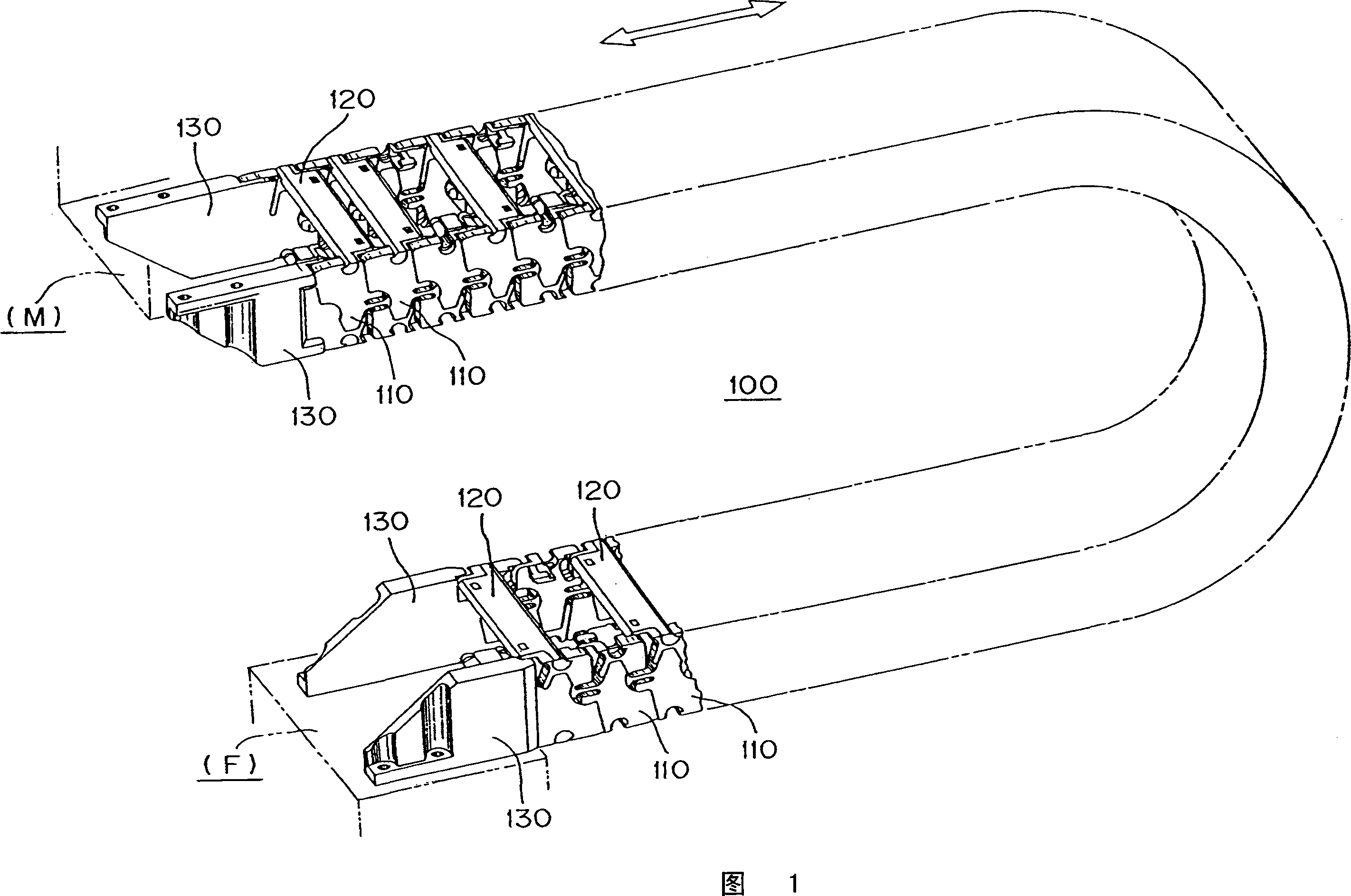
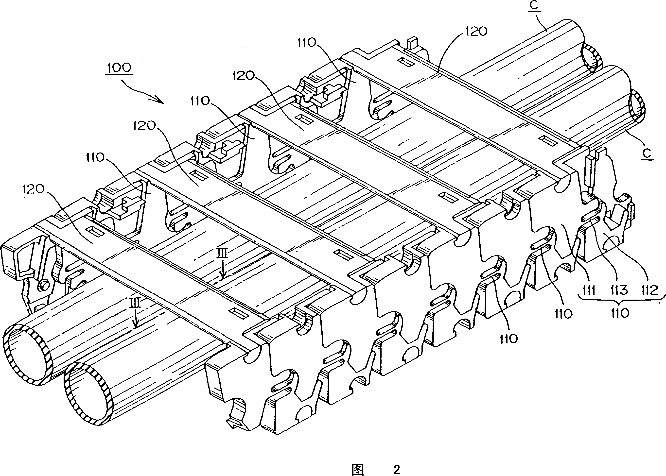
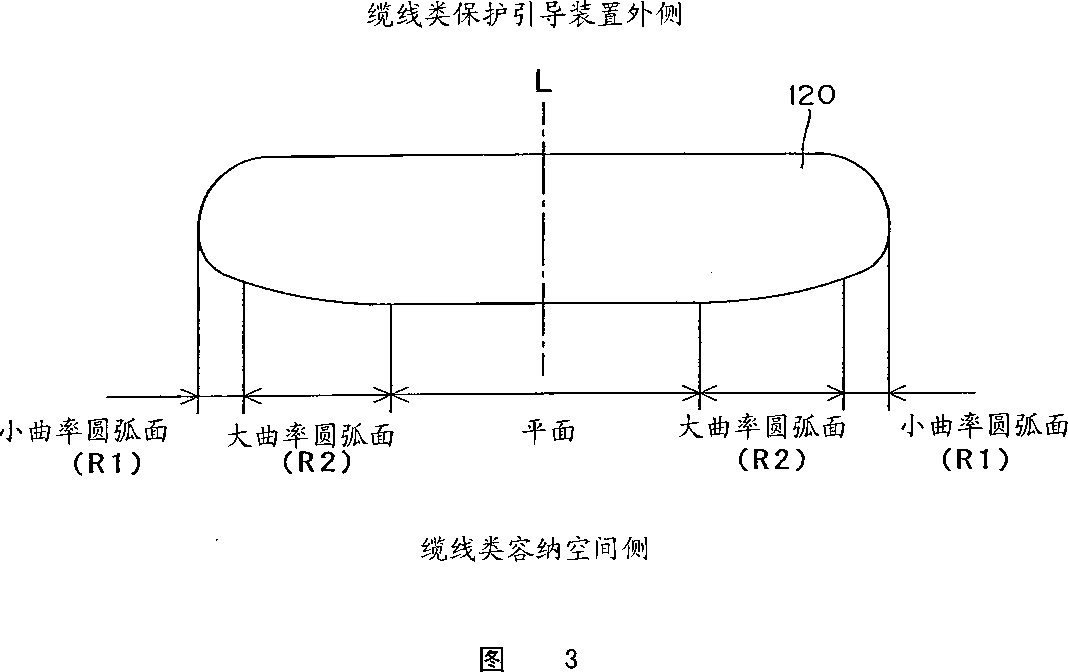
[0022] As the present invention, any cable-type protection and guide device may be used as long as it is a cable-type protection and guide device in which a plurality of pairs of left and right paired side plate assemblies arranged separately are connected from a fixed installation end to a movable installation end, and, On the curved inner peripheral side and the curved outer peripheral side of the side plate assembly, connecting plates are detachably crossed at predetermined intervals, respectively, and in the cable accommodation space surrounded by the side plate assembly and the connecting plate. , accommodating cables from the fixed installation end to the mobile installation end, wherein, the cross-sectional shape of the connecting plate in the direction from the fixed installation end to the mobile installation end is symmetrical with respect to the central vertical line, so The surface of the above-mentioned cross-sectional shape facing the side of the cable accommodati...


PUM


Abstract

The present invention provides a device for protecting and guiding cabled Yarn, which can reduce the friction induced by the contacting between the cabled yarn it contains and the ends of the linking plates, and protect from producing the wearing powder and the injury and fracture of the cabled yarn, and can reduce the wearing and the of impacting noises induced from the connect of the side platecomponents. The Section formed by the self-fixing end of the connecting plate (120) facing the mobile installing end is in symmetric structure revolving central vertical line (L). The plane of section facing the side of cabled yarn is small curvature arc surface (R1), big curvature arc surface (R2), plane surface successively, or big curvature arc surface bigger than the said big curvature arc surface, big curvature arc surface (R2), and small curvature arc surface (R1) successively, and are continuous Surface of every surface tangency to realize the purpose of the invention.

Description

technical field [0001] The present invention relates to a protection and guide device for cables, and more specifically, to a device suitable for accommodating cables such as cables or hoses for supplying energy such as electric power or compressed air to movable parts of industrial machinery, and even in A cable protection and guide device that safely and reliably supports and guides cables even when the movable part is moving. Background technique [0002] As an existing cable-type protection and guide device, a cable-type protection and guide device 500 shown in FIG. There are multiple pairs of plate assemblies 510 connected from the fixed installation end to the movable installation end, and on the curved inner peripheral side and the curved outer peripheral side of the side plate assembly 510, there are connecting plates 520 detachable at predetermined intervals. Cables are accommodated in the cable accommodation space surrounded by the plate assembly 510 and the conne...

Claims


Application Information

Patent Timeline
Patent Type & Authority Applications(China)
IPC IPC(8): F16G13/16
CPCH02G3/0475F16G13/16Y10S59/90H01B7/17
Inventor 宇泷昭彦小宫庄一郎
Owner TSUBAKIMOTO CHAIN CO
Learn More