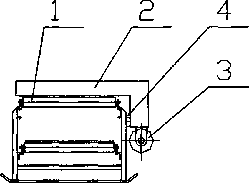
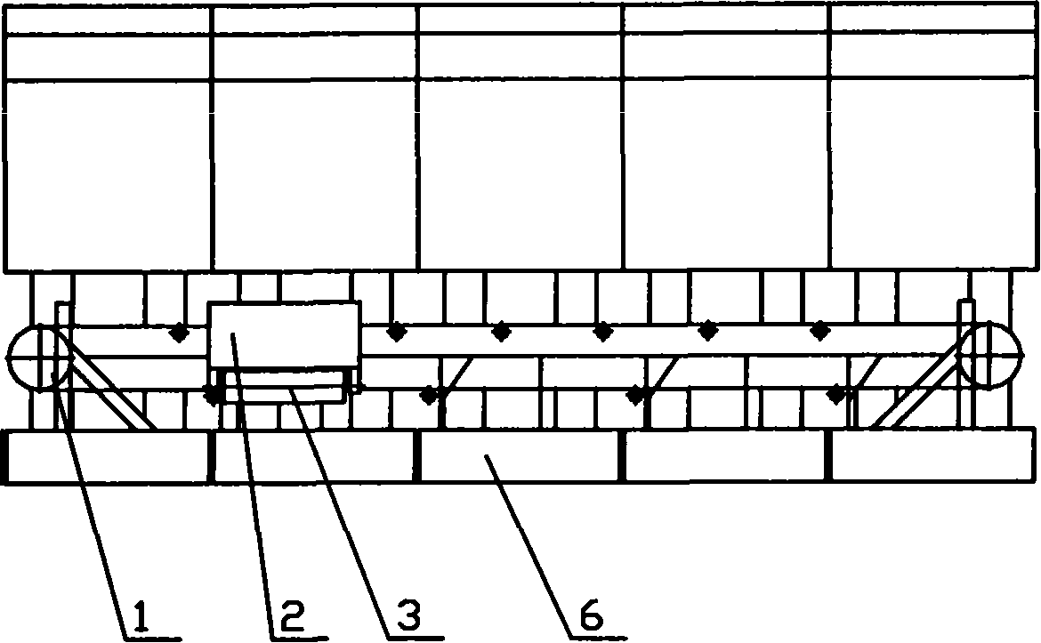
Mine goaf filling system
A technology for goafs and mines, applied in the fields of backfill, mining equipment, earth-moving drilling and mining, etc., can solve the problems of difficulty in distribution, high labor intensity, and low filling rate of goafs, eliminating the upper space and improving the filling rate. rate effect
Inactive Publication Date: 2008-06-04
ZHANGKUANG ELECTROMECHANICAL ENG TECH INST BEIJING
View PDF0 Cites 3 Cited by
- Summary
- Abstract
- Description
- Claims
- Application Information
AI Technical Summary
Problems solved by technology
[0010] The main purpose of the present invention is to overcome the defects existing in the prior art and provide a mine goaf filling system with a new structure to solve the problem of low filling rate of goaf filling, difficulty in distributing materials, low filling efficiency and labor intensity. It is a big problem, so that it can achieve the ideal effect of filling rate and filling efficiency, so it is more suitable for practical use and has industrial utilization value.
Method used
View moreImage
Smart ImageViewing Examples
Examples
Embodiment 5
[0061] The working process of the fifth embodiment is the same as that of the fourth embodiment.
Login to View More PUM
 Abstract
The invention discloses a mine stowage system, comprising a continuous conveyer, an unloader, a flinger and a guide rail, wherein the continuous conveyer is arranged on the work station, the unloader is arranged on the continuous conveyer and can move lengthwise along the continuous conveyer, the flinger is arranged on the unloader and provided with a flinging head which is a rotating member and can rotate around the axial line of the flinging head; the filling materials are conveyed to the unloader by the continuous conveyer and unloaded from the continuous conveyer by the unloader, the unloaded materials are placed on the flinging head of the flinger, the flinging head which rotates at a high speed flings the unloaded materials to the filling face; because the unloader can move lengthwise along the continuous conveyer, the invention can fling materials to the filling face on different positions in the longitudinal direction of the continuous conveyer, which resolves the problem that the mine goaf is filled up with solid materials in large area and gross section and realizes the band filling along the longitudinal direction of the continuous conveyer. The invention is applicable to large area filling in all underground mine goaf.
Description
technical field [0001] The invention relates to a mine filling system in the field of mining machinery, in particular to a movable mine goaf filling system. Background technique [0002] Taking the ground pressure management method during mining as the main classification basis, the mining methods of underground mines mainly include empty field method, caving method and filling method. Among them, the caving method is rarely used in the design, while the filling method is used more in recent years, and has a certain development prospect. [0003] In the 21st century, mining will turn to deep ore bodies, "three lower ore bodies" and other complex and difficult ore bodies. The problem of ground pressure control will become increasingly prominent and become the main obstacle to efficient and safe operations in deep areas. Goaf filling is one of the effective ways to control ground pressure in deep and complex stress environments. Therefore, more and more people pay attention ...
Claims
Login to View More Application Information
Patent Timeline
 IPC IPC(8): E21F15/06
Inventor 孙浩巩长勇姜福星景武李建国宋曦吴淼马星民董柏峰王黔兴刘元成
Owner ZHANGKUANG ELECTROMECHANICAL ENG TECH INST BEIJING
Features
- Generate Ideas
- Intellectual Property
- Life Sciences
- Materials
- Tech Scout
- Unparalleled Data Quality
- Higher Quality Content
- 60% Fewer Hallucinations
Learn More Browse by: Latest US Patents, China's latest patents, Technical Efficacy Thesaurus, Application Domain, Technology Topic, Popular Technical Reports.
© 2025 PatSnap. All rights reserved.Legal|Privacy policy|Modern Slavery Act Transparency Statement|Sitemap|About US| Contact US: help@patsnap.com


