
Flexible valve

A flexible sleeve and sleeve technology, applied in the field of flexible valves, can solve the problems of short service life of sleeve valve, return of flushing water, large sleeve strain, etc., and achieve the effect of long service life

Inactive Publication Date: 2008-05-28
SEMVAC AS
View PDF3 Cites 4 Cited by
  • Summary
  • Abstract
  • Description
  • Claims
  • Application Information

AI Technical Summary

Problems solved by technology

[0014] Another disadvantage is that known sleeve valves have a relatively short service life because, as is the case most of the time, the valve is closed when the strain on the sleeve is considerable
[0015] In addition, the valves do not close with the often required certainty, and rupture of the membrane may further lead to more or less return of flushing water from within the vacuum fitting

Method used


Image

  • Flexible valve
  • Flexible valve
  • Flexible valve

Examples


Embodiment Construction

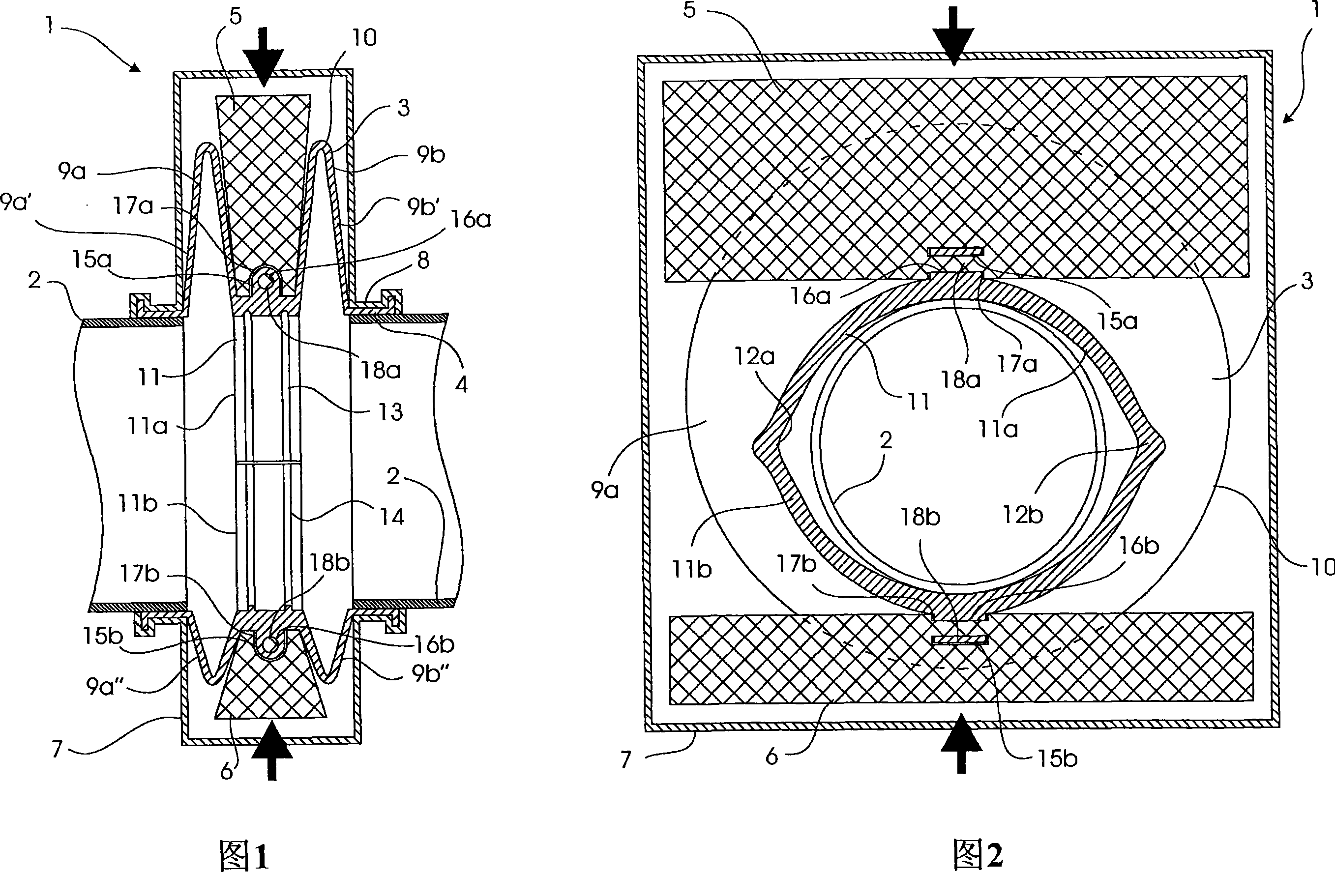
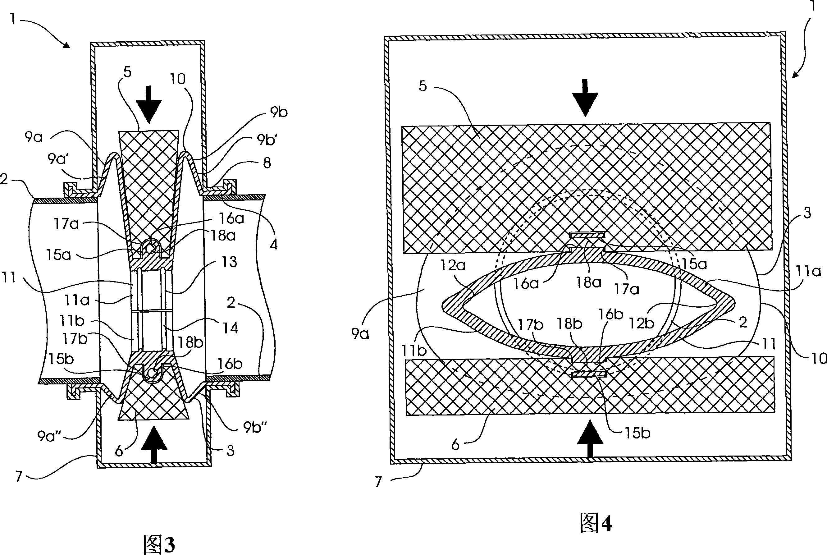
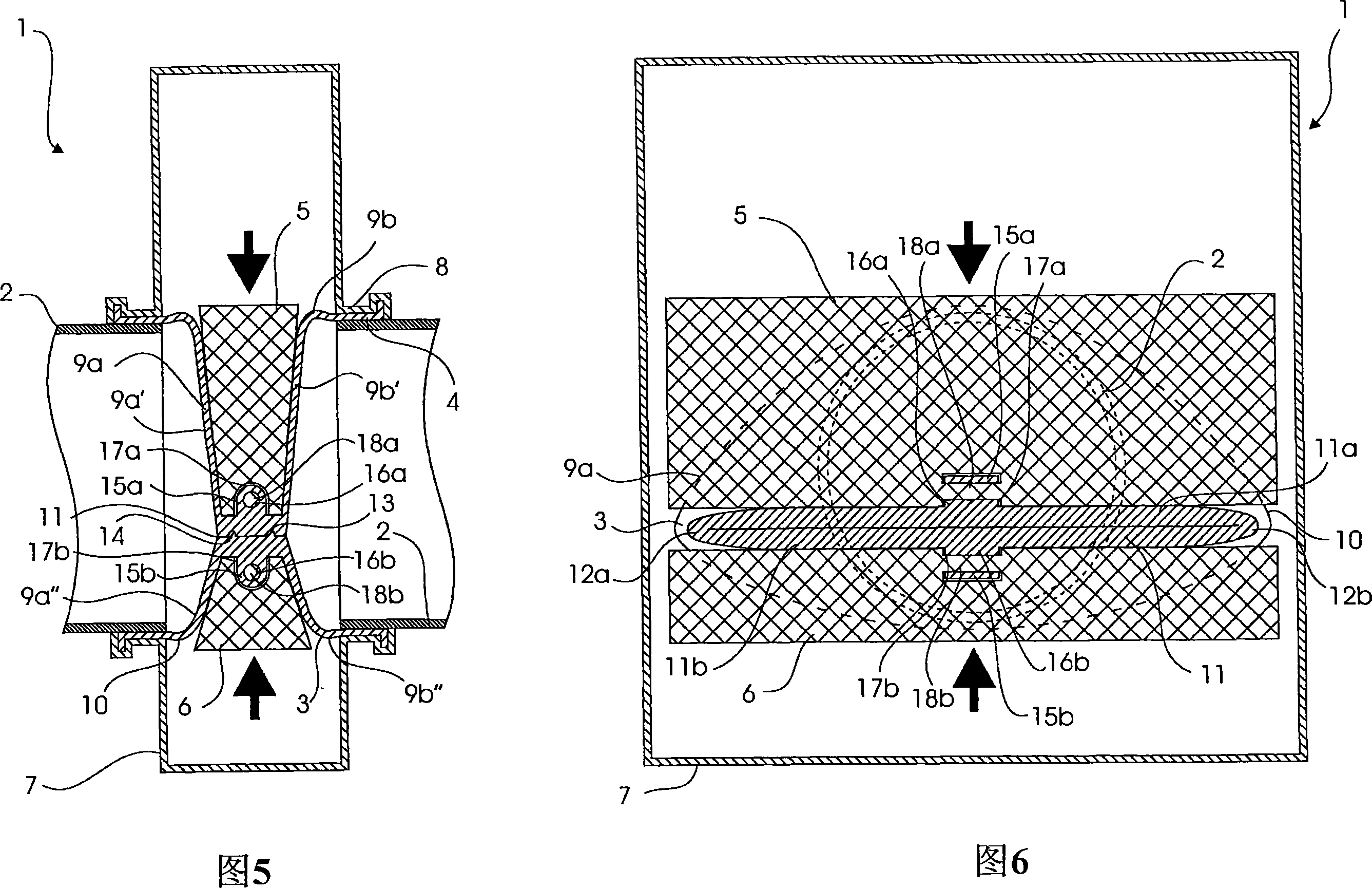
[0053] In the following it is assumed that the valve 1 according to the invention in FIGS. 1 to 6 is installed in a drain line 2 from a sanitary fitting (not shown) in a replaceable sanitary fitting module (not shown). The space available within such modules is limited, so it is important that the valves have a short built-in length and a small width in transverse direction so that the valves can fit within the modules.

[0054] The valve comprises a sleeve 3 tightly connected to a drain line 2 with a pipe connection 4, and an upper side 5 and a lower side 6 displaceable back and forth in opposite phases.

[0055] The sleeve and slide are surrounded by a closed housing 7 of the pipe connection 4 tightly connected to the sleeve by other pipe connections 8 .

[0056] The sleeve is formed with two circumferential folds 9a and 9b with an upper part 9a', 9b' and a lower part 9a", 9b". Seen in axial section, the fold in this case is mainly shaped as a V with an apex angle in the in...


PUM


Abstract

A flexible valve that includes a flexible sleeve inserted in a fluid line and made with two circumferential folds, two opposite slides located between the folds displaceably in phase opposition and extending crosswise of the sleeve, and a mechanism for displacing the slides between open an closed positions. A sleeve section connects the two folds, and a closing section made on the sleeve section is supported by the slides. The flexible valve according to the invention has a longer service life and a shorter installation length than hitherto known. It is suitable for use as stop valve in the drain line from a toilet in a railway carriage, in which it can be continuously kept in the closed position without applying energy, and it is furthermore safeguarded against impurities getting out into and fouling the surrounding environment in the railway carriage.

Description

technical field [0001] The invention relates to a valve for opening and closing a flow in a fluid line, the valve comprising: a flexible sleeve inserted in the space between two free line ends in the fluid line; two spaced transverse folds connected directly or indirectly to each of said two pipe ends; a sleeve portion connecting said two folds; formed in said sleeve a closing portion on the barrel portion; two opposing slides engaged with each side of the closing portion; and means for displacing the slides between a position in which they cause the closing portion to close and a second position in which the closing portion remains open. device. [0002] The invention also relates to the method of manufacture of the valve and the use of the valve. Background technique [0003] Purely mechanical valves are mainly used as shut-off valves in fluid lines. Mentioned as an example are slide valves in the drain line of a sanitary fitting, where the sliding valve can advantageou...

Claims


Application Information

Patent Timeline
Patent Type & Authority Applications(China)
IPC IPC(8): F16K7/06
CPCF16K7/06
Inventor 汉斯·克里斯蒂安·加贝尔戈德
Owner SEMVAC AS
Learn More