Location update method and system

A configuration method and location area technology, applied in the field of communication systems, can solve the problems of wasting air interface resources, affecting network quality, and non-overlapping, etc., to achieve the effect of ensuring access performance

Inactive Publication Date: 2008-05-28
HUAWEI TECH CO LTD
View PDF0 Cites 23 Cited by
  • Summary
  • Abstract
  • Description
  • Claims
  • Application Information

AI Technical Summary

Problems solved by technology

[0008] However, for the above location update method, there are the following problems: when the location areas are divided, they are closely connected but do not overlap each other, such as figure 1 The shown location area L1 and location area L2, therefore, the terminal at the junction of the two location areas will frequently update the location area when the terminal frequently reselects cells due to the back and forth movement of the location, so that Trigger a large number of location area update messages, that is, location update messages
[0010] 1. The terminal at the boundary of the location area cannot freely choose the cell that is most suitable for camping, especially when the signal of each cell at the junction is not good, the terminal cannot freely select the cell with the best signal, which will make it difficult for mobile The user paging success rate and the connection rate of the terminal decrease, which in turn affects the quality of the network and wastes air interface resources. In today's increasingly tense air interface resources, this waste of air interface resources is extremely unwise
[0011] 2. Even if the threshold is set to limit the frequent location update of terminals at the junction of location areas, for densely populated urban areas, when the cell radius is small, terminals at the junction of location areas can still easily cross the cell, so that It is easy for the terminal to meet the above threshold and cause location updates to occur

Method used


Image

  • Location update method and system
  • Location update method and system
  • Location update method and system

Examples


Embodiment Construction

[0055] In order to make the purpose, technical means and advantages of the embodiments of the present invention clearer, the present invention will be further described in detail below with reference to the accompanying drawings and examples.

[0056] Embodiments of the present invention provide a comprehensive solution to the problem of frequent location updates when cell reselection occurs, enabling users to select the most suitable cell for camping on according to actual needs without causing frequent location updates. The solution includes four aspects:

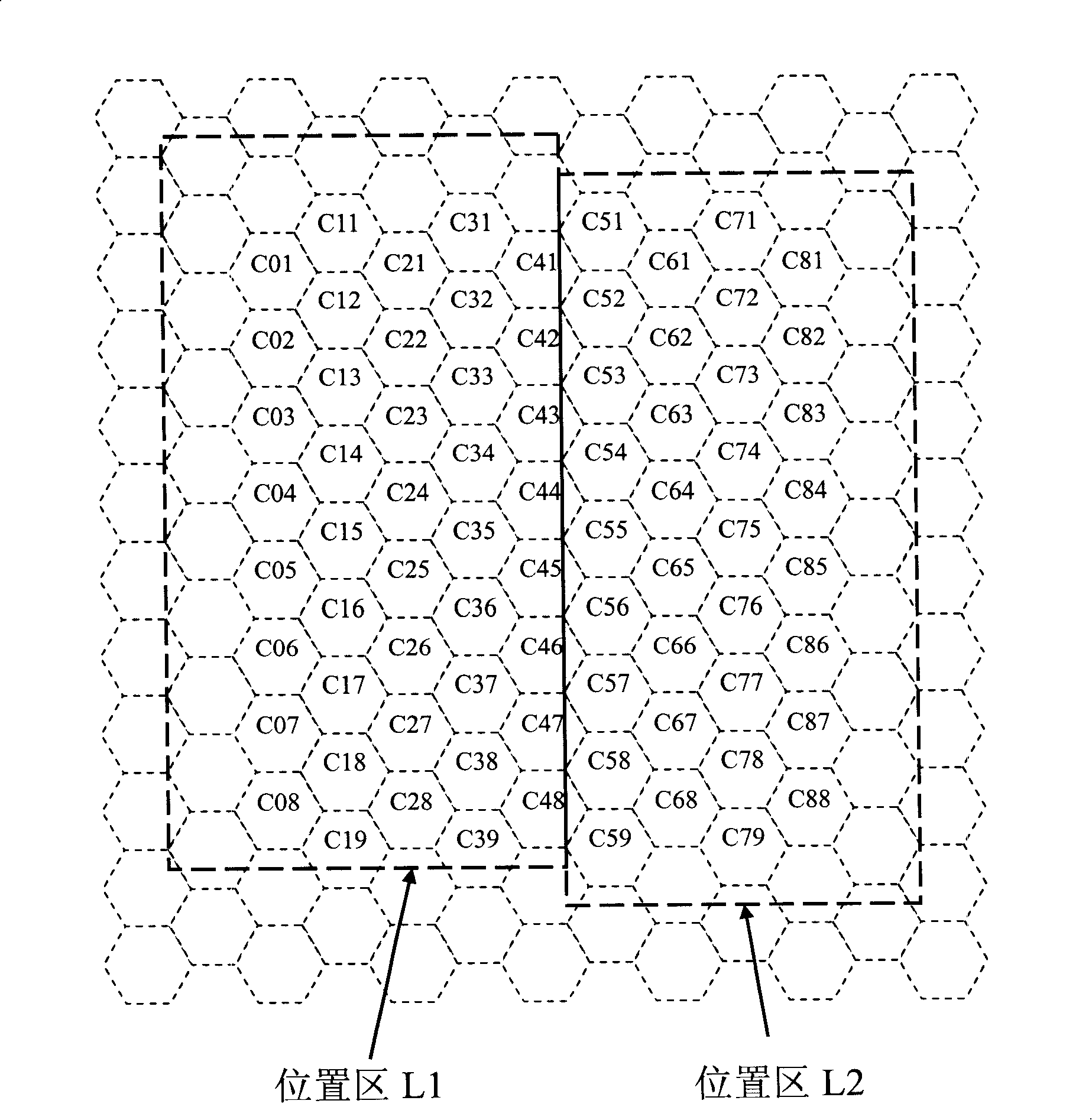
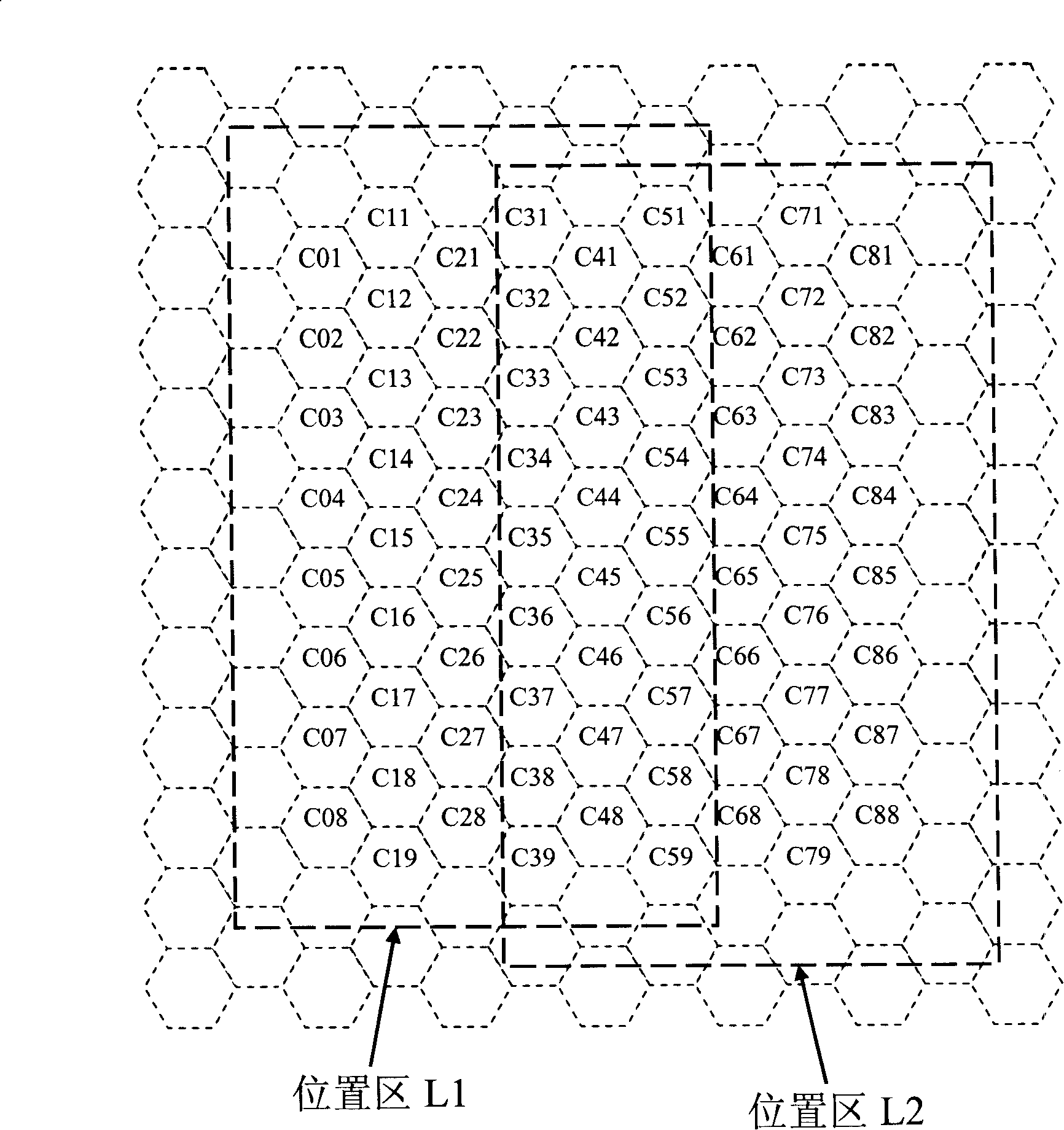
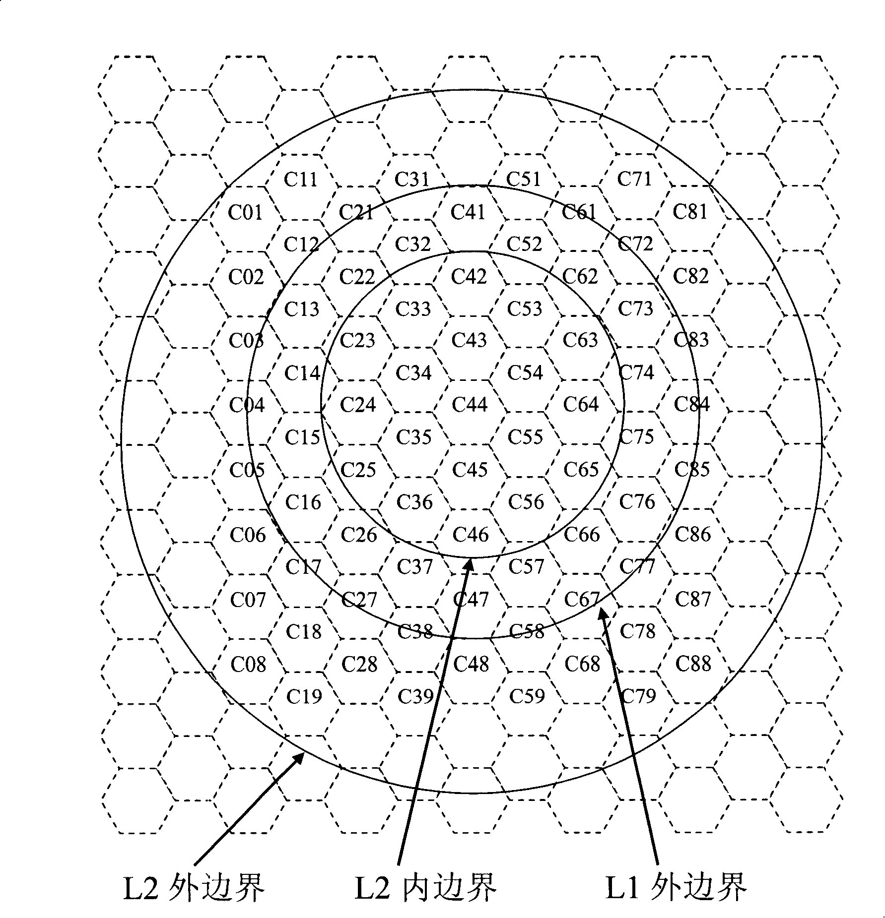
[0057] First, an embodiment of the present invention provides a location area configuration method, so that cells at the junction of two adjacent location areas in a certain area are located in the two location areas at the same time.

[0058] Secondly, since the same cell is located in two location areas at the same time, the present invention also provides a method for the cell to broadcast location areas, so as to noti...


PUM


Abstract

The embodiment of the invention discloses a location updating method, and the current location area marking information is stored in a terminal. The method comprises the following steps: when the terminal carries out cell reselection, whether the cell to be selected of the terminal is positioned in the current location area is judged, if yes, the location updating is not carried out; if not, the location area which is jointly owned by the cell to be selected and the current residing cell is taken as an objective location area, so as to carry out the location updating. After the method in the embodiment of the invention is adopted to carry out the location updating, the terminal which is positioned at the boundary of the location area can carry out the repeated cell reselection without causing frequent location area updating, thereby further selecting the cell which is most suitable to be resided to stay and guaranteeing the access performance of the terminal. The embodiment of the invention also discloses a location updating system, a location area collocation method, a cell broadcasting location area method and a paging method.

Description

technical field [0001] The invention relates to communication system technology, in particular to a location update method and system. Background technique [0002] In the communication system, there will be countless cells, which are the basic units of the mobile communication network. Each cell corresponds to a base station. A base station is generally configured with one or more cells. Each cell is responsible for the call task in the cell. . There are usually two ways for a call center to call a called party: if the call center knows where the called party is, then paging directly at the called party’s position; To call to the called party, it is necessary to perform network-wide paging. [0003] Specifically, in the GSM communication system, there are many cells under one switch. When the mobile switching center (MSC) wants to call a terminal, if the MSC knows the cell where the terminal is currently located, it will directly paging in the cell where the terminal is l...

Claims


Application Information

Patent Timeline
IPC IPC(8): H04Q7/38H04B7/26H04W60/04
CPCH04W60/04
Inventor 王正伟
Owner HUAWEI TECH CO LTD
Why Eureka
Try Eureka