
Image dithering correcting unit, image dithering correcting device, photographing apparatus and portable equipment

A jitter correction and image technology, applied in projection devices, printing devices, image communication and other directions, can solve the problems of inability to perform, fit and fall off, etc.

Inactive Publication Date: 2008-05-21
FUJI PHOTO OPTICAL CO LTD
View PDF3 Cites 28 Cited by
  • Summary
  • Abstract
  • Description
  • Claims
  • Application Information

AI Technical Summary

Problems solved by technology

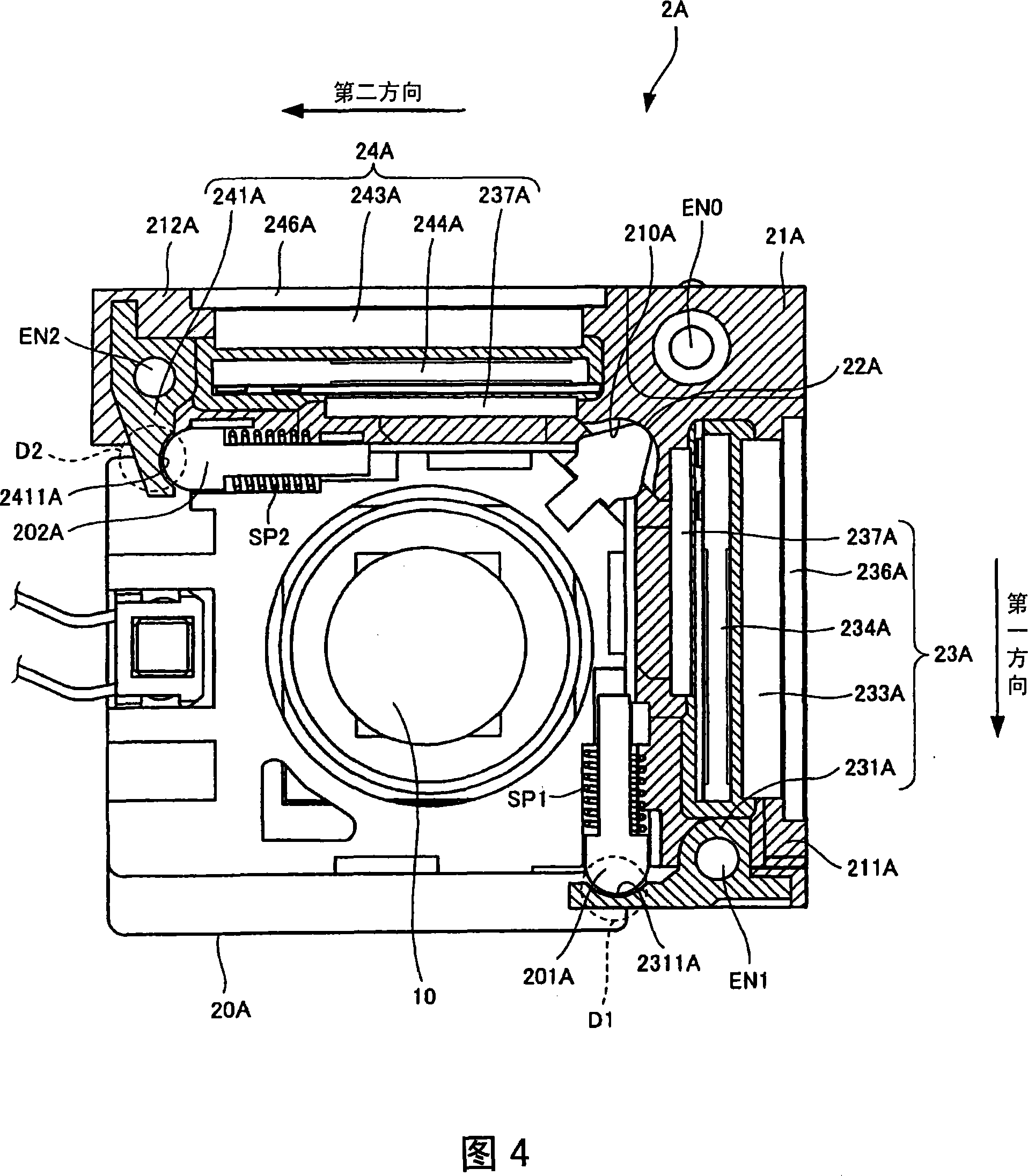
[0018] However, when the portable device equipped with the image shake correction unit of FIG. 17 is dropped in the configuration shown in FIG. The cooperation of the ball fitting part 202 with the holding module 20 and the support member 241 will fall off, resulting in failure to perform normal actions in the future

Method used


Image

  • Image dithering correcting unit, image dithering correcting device, photographing apparatus and portable equipment
  • Image dithering correcting unit, image dithering correcting device, photographing apparatus and portable equipment
  • Image dithering correcting unit, image dithering correcting device, photographing apparatus and portable equipment

Examples


Embodiment Construction

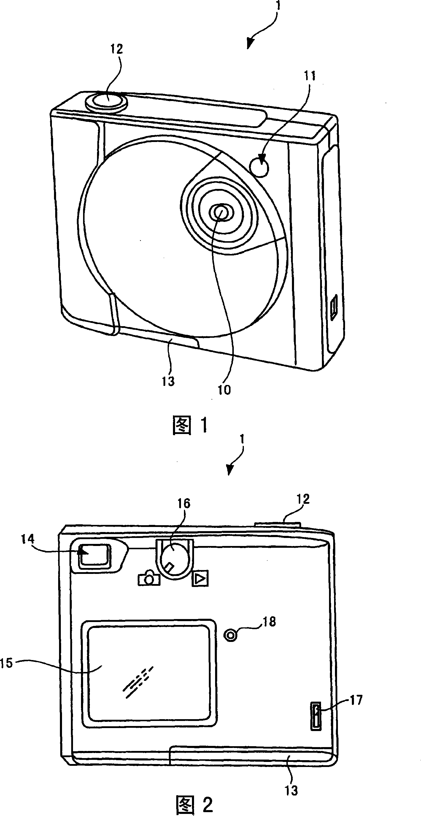
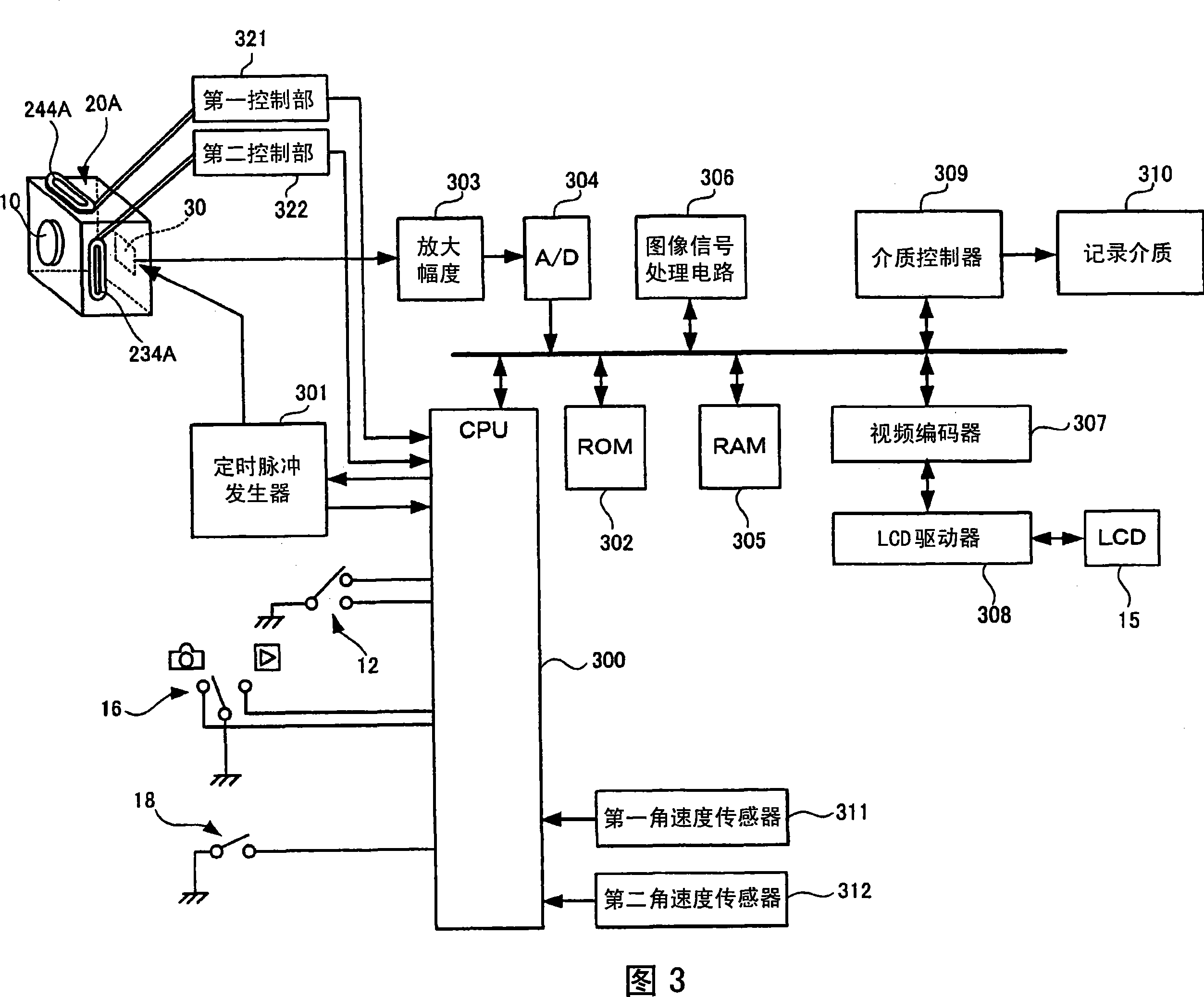
[0082]Next, preferred embodiments of an image shake correction unit and an image shake correction device including the image shake correction unit according to the present invention will be described in detail with reference to FIGS. 1 to 9 . Here, since the embodiments described below are specific examples of the image shake correction unit and the image shake correction device including the image shake correction unit of the present invention, various technically preferable limitations are added, but in the following The scope of the present invention is not limited to these aspects unless the description of the present invention is particularly limited in the description.

[0083] 1 is an external perspective view of a digital camera according to one embodiment of an image blur correction unit and an image blur correction device including the image blur correction unit according to the present invention, viewed obliquely from above.

[0084] The digital camera 1 described i...


PUM


Abstract

The present invention discloses an image shake correction unit, in which a first movement limiting member (2021A) for limiting the movement range of a lens optical axis direction of a holding module is respectively provided at a first driving point (D1) and a second driving point (D2). ), the second movement limiting member (2031A). The movement range of the holding module (20A) in the optical axis direction is limited to the first driving point (D1) and The second driving point ( D2 ) is within a range in which the cooperation between each convex portion provided respectively and each concave portion receiving the convex portion is ensured. Therefore, it is possible to provide an image shake correction unit that can accurately perform shake correction even after a shock is applied due to a fall, an image shake correction device including the image shake correction unit, an imaging device including the image shake correction device, and a The portable device of the photography device.

Description

technical field [0001] The present invention relates to an image shake correction unit that can be used as a hand shake correction mechanism in photographing devices such as a digital camera or a mobile phone with a camera, an image shake correction device including the image shake correction unit, and a device including the image shake correction device. A photographing device and a portable device equipped with the photographing device. Background technique [0002] Conventionally, in digital cameras and the like, various hand-shake correction mechanisms have been employed in order to suppress disturbance of photographed images due to user's hand-shake or the like (see Patent Documents 1, 2, and 3). [0003] As such a camera shake correction mechanism, what is called a so-called gimbal mechanism is used to keep the module rotatable in pitching and yawing directions. [0004] However, in the case of the universal joint structure disclosed in Patent Document 1, since it is ...

Claims


Application Information

Patent Timeline
Patent Type & Authority Applications(China)
IPC IPC(8): G03B5/00H04N5/225
Inventor 关野静雄
Owner FUJI PHOTO OPTICAL CO LTD
Learn More