Closed-loop control method and apparatus of optical fibre gyro system
A fiber optic gyroscope and digital system technology, applied in Sagnac effect gyroscopes and other directions, can solve the problems of long rise time, poor dynamic error, reduced dynamic sensitivity and response speed of data processors, etc., to improve dynamic sensitivity and response. speed, optimizing output signal, reducing the effect of dynamic errors
Inactive Publication Date: 2010-12-01
BEIHANG UNIV
View PDF0 Cites 0 Cited by
- Summary
- Abstract
- Description
- Claims
- Application Information
AI Technical Summary
Problems solved by technology
Since the control algorithm adopted by the data processor in the prior art is an integral algorithm, those skilled in the art can easily know that the dynamic sensitivity and response speed of the data processor will decrease when the integral algorithm is used, which will lead to a relatively large dynamic error of the system. Poor, long rise time, low dynamic tracking ability
Method used
View moreImage
Smart ImageViewing Examples

Examples
Embodiment 1
Login to View More PUM
 Abstract
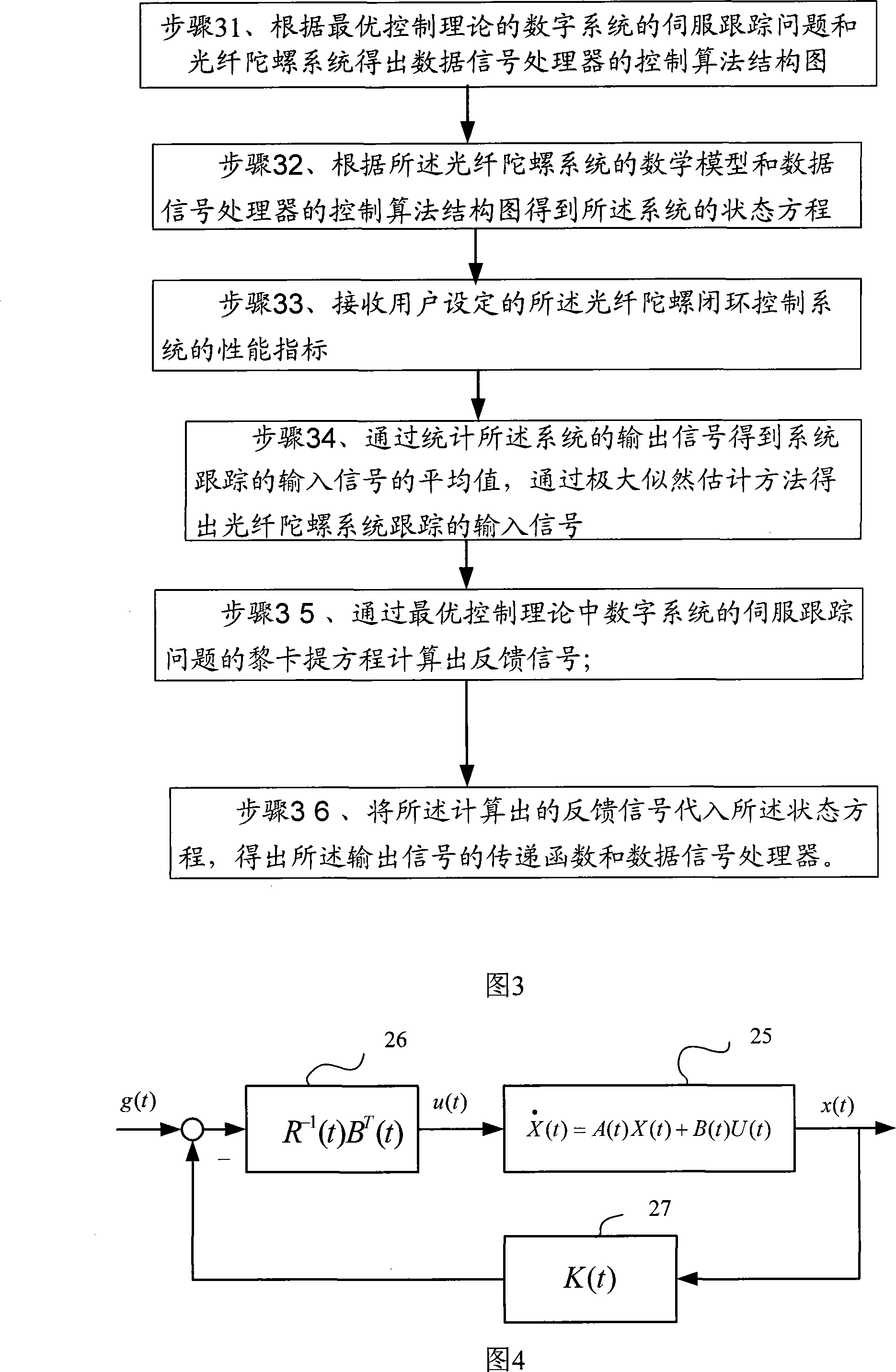
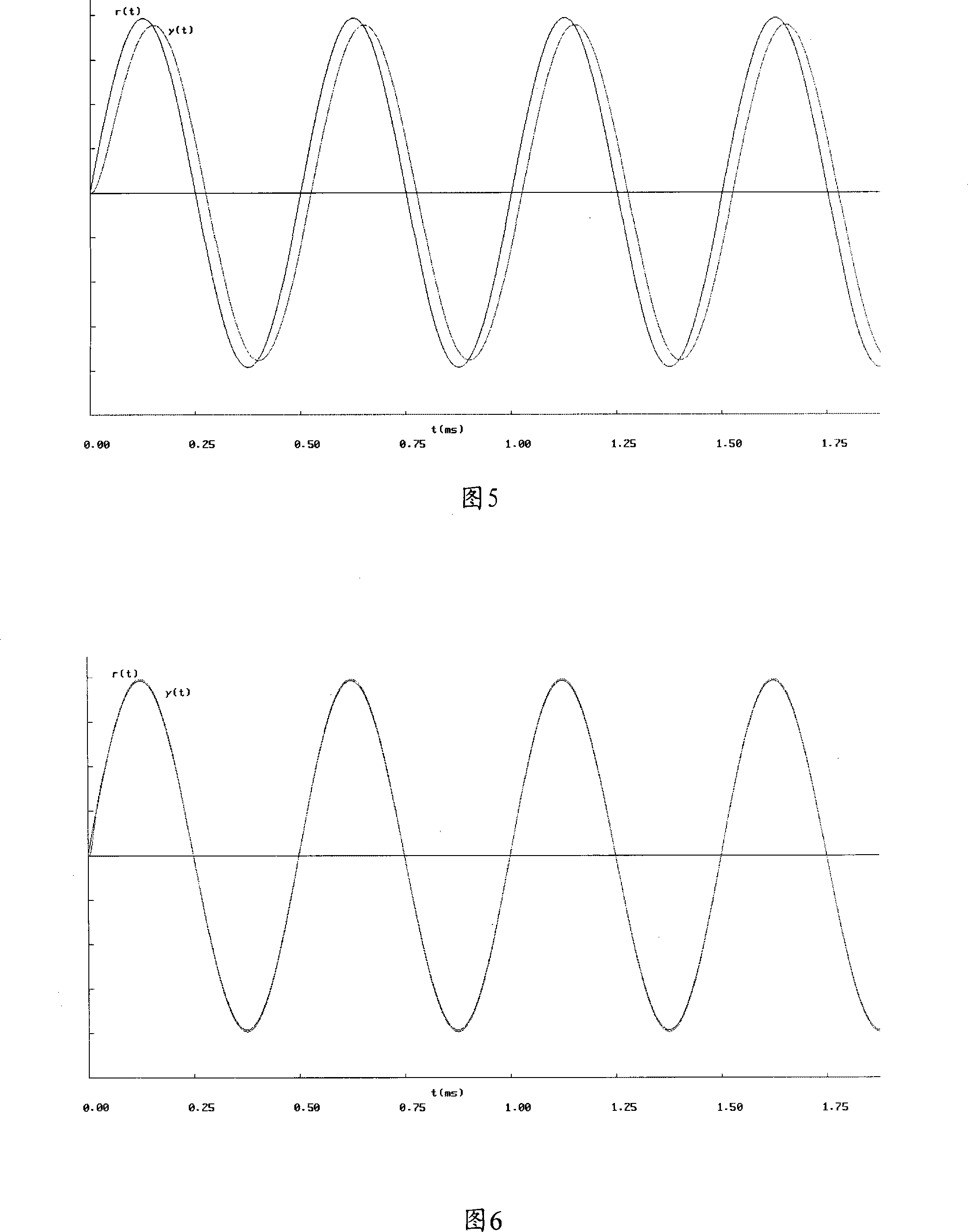
The invention provides a closed loop control method of a fiber optic gyroscope system and a device thereof. The closed loop control method and the device thereof belong to the technical field of the fiber optic gyroscope. The method comprises that an inputted signal passes through a detector, an anterior discharge filter circuit, an A / D converter and a data signal processor sequentially and then an outputted signal is acquired; the data signal processor also adopts the outputted signal as a feedback signal and the feedback signal passes through a D / A converter, a driver and a Y waveguide modulator to counteract the inputted signal Sagnac phase of the fiber optic gyroscope to form the closed loop control. The method comprises that the maximum likelihood estimation method is adopted to obtain the inputted signal followed by the fiber optic gyroscope system; the data signal processor is work out with the servo-tracking problem of the digital system of the optimal control theory. The specific practical implementation way of the invention also provides a data signal processor device. The method and the device have the advantages that the method and the device can improve the dynamic sensitivity of the fiber optic gyroscope system and the dynamic tracking ability of the system.
Description
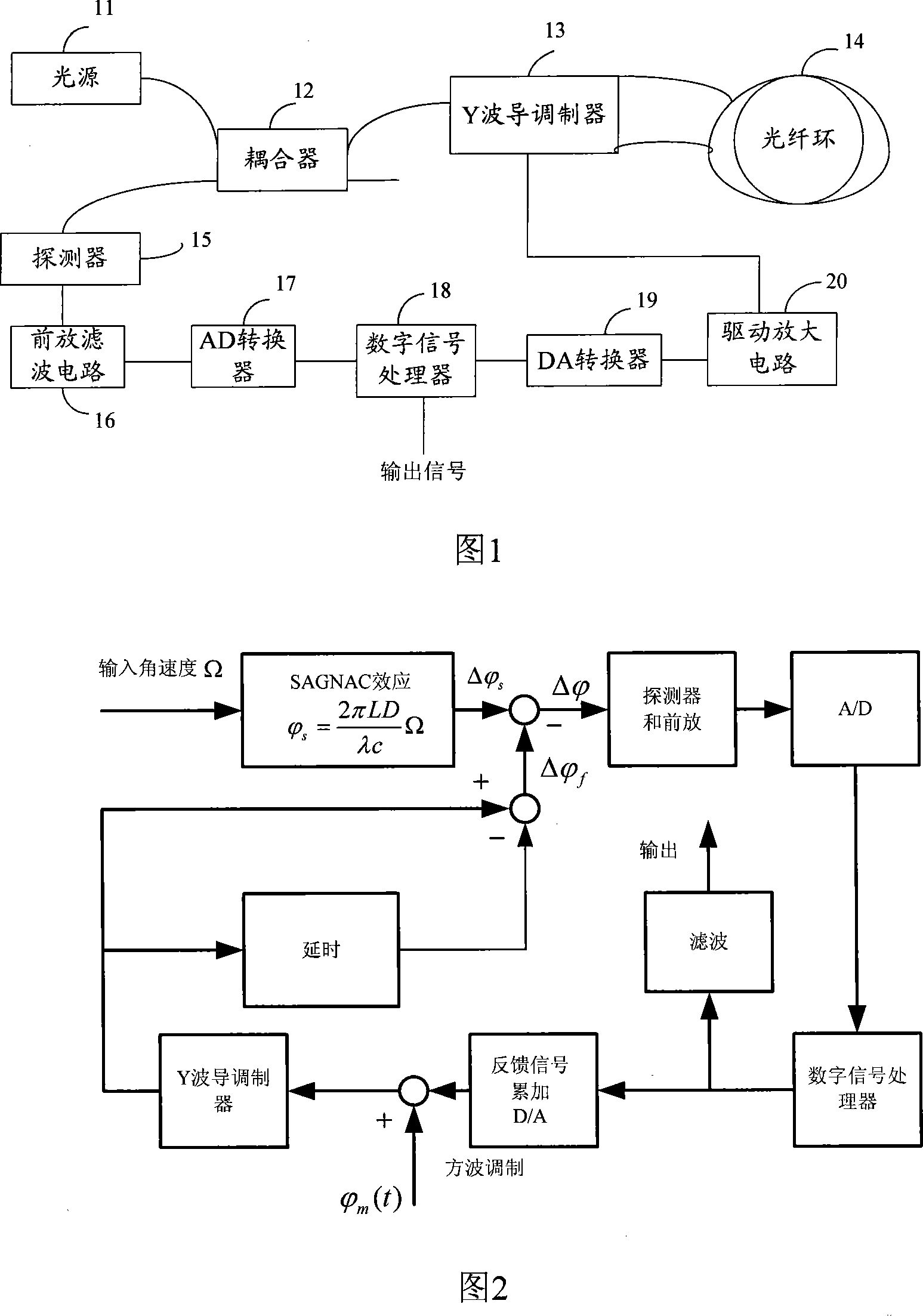
Closed-loop control method and device for fiber optic gyro system technical field The invention relates to the technical field of fiber optic gyroscopes, in particular to a closed-loop control method and device for a fiber optic gyroscope system. Background technique The fiber optic gyroscope system is a widely used device that is sensitive to angular motion relative to inertial space. As an important inertial sensor, it is used to measure the attitude angle and angular velocity of the vehicle, and is the core component of the inertial system. It is used in aircraft navigation, ship navigation and land navigation. Interferometric fiber optic gyro is an instrument for measuring angular velocity. Its hardware is shown in Figure 1, including light source 11, coupler 12, Y waveguide modulator 13, fiber optic ring 14, detector 15, pre-amp filter circuit 16, AD conversion device 17 , digital signal processor 18 , DA converter 19 and driving amplifying circuit 20 . The worki...
Claims
Login to View More Application Information
Patent Timeline
 Patent Type & Authority Patents(China)
IPC IPC(8): G01C19/72
Inventor 张春熹李慧李立京宋凝芳潘雄许文渊
Owner BEIHANG UNIV
Features
- R&D
- Intellectual Property
- Life Sciences
- Materials
- Tech Scout
- Unparalleled Data Quality
- Higher Quality Content
- 60% Fewer Hallucinations
Learn More Browse by: Latest US Patents, China's latest patents, Technical Efficacy Thesaurus, Application Domain, Technology Topic, Popular Technical Reports.
© 2025 PatSnap. All rights reserved.Legal|Privacy policy|Modern Slavery Act Transparency Statement|Sitemap|About US| Contact US: help@patsnap.com