
Magnetizer drilling jig gripper for electro-hydraulic servo valve

A technology of electro-hydraulic servo valve and magnetizer, which is applied in the direction of drilling jigs for workpieces, etc., can solve problems such as inaccurate positioning, and achieve the effects of improving processing efficiency, convenient processing, and convenient positioning

Inactive Publication Date: 2008-05-14
SHANGHAI NUOMA HYDRAULIC SYST
View PDF0 Cites 6 Cited by
  • Summary
  • Abstract
  • Description
  • Claims
  • Application Information

AI Technical Summary

Problems solved by technology

[0004] The technical problem to be solved by the present invention is to provide an electro-hydraulic servo valve magnetic conductor drilling jig, which has solved the defect of inaccurate positioning in the prior art

Method used


Image

  • Magnetizer drilling jig gripper for electro-hydraulic servo valve
  • Magnetizer drilling jig gripper for electro-hydraulic servo valve

Examples


Embodiment 1

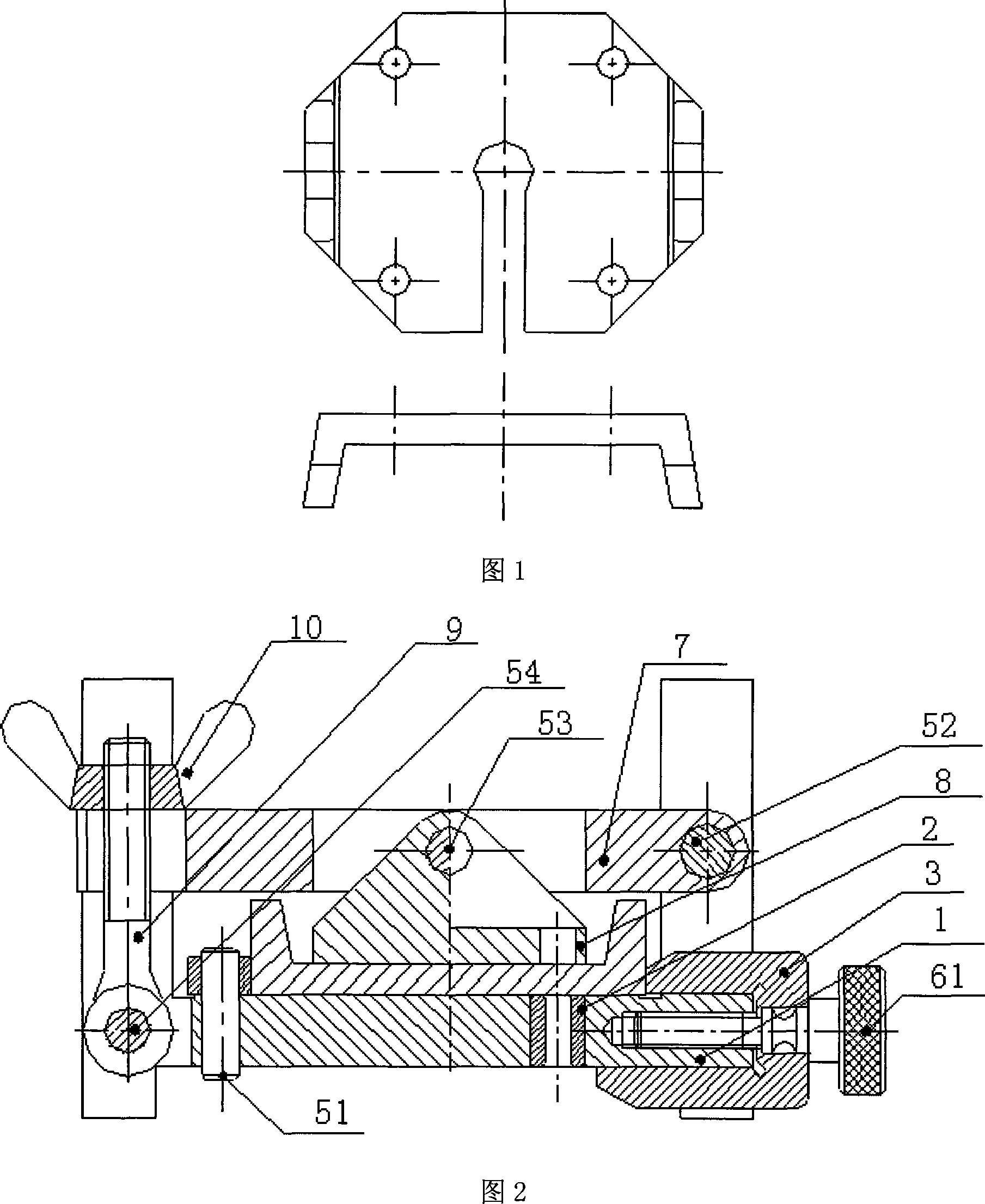
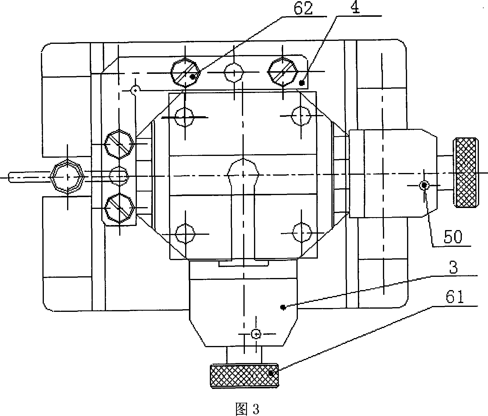
[0016] As shown in Figures 1, 2, and 3, an electro-hydraulic servo valve magnet guide jig fixture includes a jig body 1, a drill sleeve 2, a positioning plate 4, a cylindrical pin 51, two sliding positioning plates 3, screws 61, Elastic straight pin 50, support plate 8, screw 62, straight pin 52, rotary plate 7, straight pin 53, straight pin 54, joint bolt 9, butterfly nut 10. in:

[0017] Drilling template body 1 is an "H" type structure, which is convenient for clamping. There is a position in the middle to cooperate with drill bushing 2 and positioning plate 4, and a position for cooperating with screw 61, sliding positioning plate 3 and rotary plate 7 is provided on one side. "U"-shaped structure, the other side is provided with "U"-shaped structure that cooperates with swing bolt 9, and the front is provided with the position that cooperates with screw 61, sliding positioning plate 3, has formed a by positioning plate 4, screw 61 The positioning structure that cooperates...


PUM


Abstract

The invention relates to a drilling die and clamp for an electro-hydraulic servo valve magnetizer, comprising a jig body (1), a drill sleeve (2), a horizontal positioning mechanism, and a compaction mechanism. The invention is characterized in that: the drill sleeve (2) is tightly matched in a mounting hole of the jig body; the horizontal positioning mechanism comprises an L-shape positioning plate (4) and two U-shape slide positioning plates (3); wherein, the L-shape positioning plate is arranged on an installation position on the jig body and is fixed on the jig body through a Straight pin (51) and a screw (62); a through hole is arranged at the bottom of the U-shape slot of the slide positioning plate, and a magnetizer is positioned through one end of the U-shape slot. The invention has the advantages of convenient magnetizer positioning, convenient manufacturing of locating holes on the magnetizer, assurance of consistency of positioning precision for repetitious installation of jigs, improvement of work efficiency, and less requirements to the technological levels of workers while assuring demands of manufacturing.

Description

technical field [0001] The invention relates to a machining fixture for precision small parts, in particular to a drilling mold fixture for a magnetic conductor of an electro-hydraulic servo valve. Background technique [0002] The electro-hydraulic servo valve is an electro-hydraulic servo control component with high precision and high dynamic response used in the electro-hydraulic control system, which can be used in the hydraulic control system of precise displacement, speed, force and acceleration. The magnetizer is an important part of the electro-hydraulic servo valve, and its physical properties are very demanding. It is a key part of the torque motor of the electro-hydraulic servo valve. Its structure is shown in Figure 1. [0003] If the machining accuracy cannot be accurately positioned, the performance of the torque motor will be reduced and the service life will be reduced. In addition, the fixtures in the prior art are inconvenient to use, and the technical req...

Claims


Application Information

Patent Timeline
Patent Type & Authority Applications(China)
IPC IPC(8): B23B47/28
Inventor 曹勇雷振吴越
Owner SHANGHAI NUOMA HYDRAULIC SYST
Learn More