Switch

A technology of switches and fixed contacts, applied in the field of switches, can solve the problems that switches cannot be manufactured cheaply, achieve the effects of saving precious metals, good operating tactile feeling, and ensuring contact reliability

Inactive Publication Date: 2008-05-07
ORMON CORP
View PDF1 Cites 4 Cited by
  • Summary
  • Abstract
  • Description
  • Claims
  • Application Information

AI Technical Summary

Problems solved by technology

Therefore, the switch has a problem that it cannot be manufactured cheaply

Method used


Image

  • Switch
  • Switch
  • Switch

Examples


Embodiment Construction

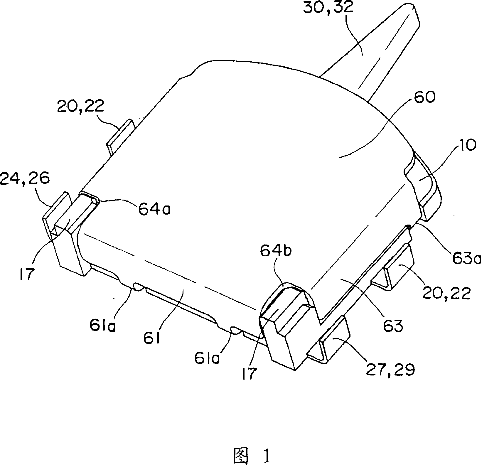
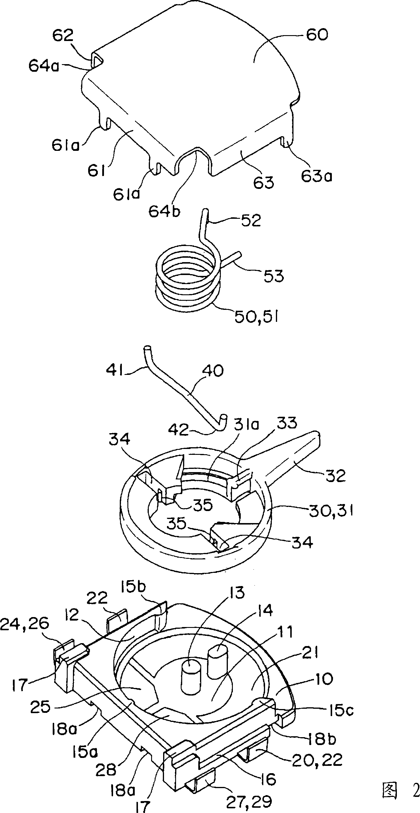
[0053] Embodiments of the present invention will be described based on FIGS. 1 to 11 .

[0054] As shown in FIGS. 1 to 8 , the first embodiment is applied to a small switch that is surface-mounted on a printed circuit board.

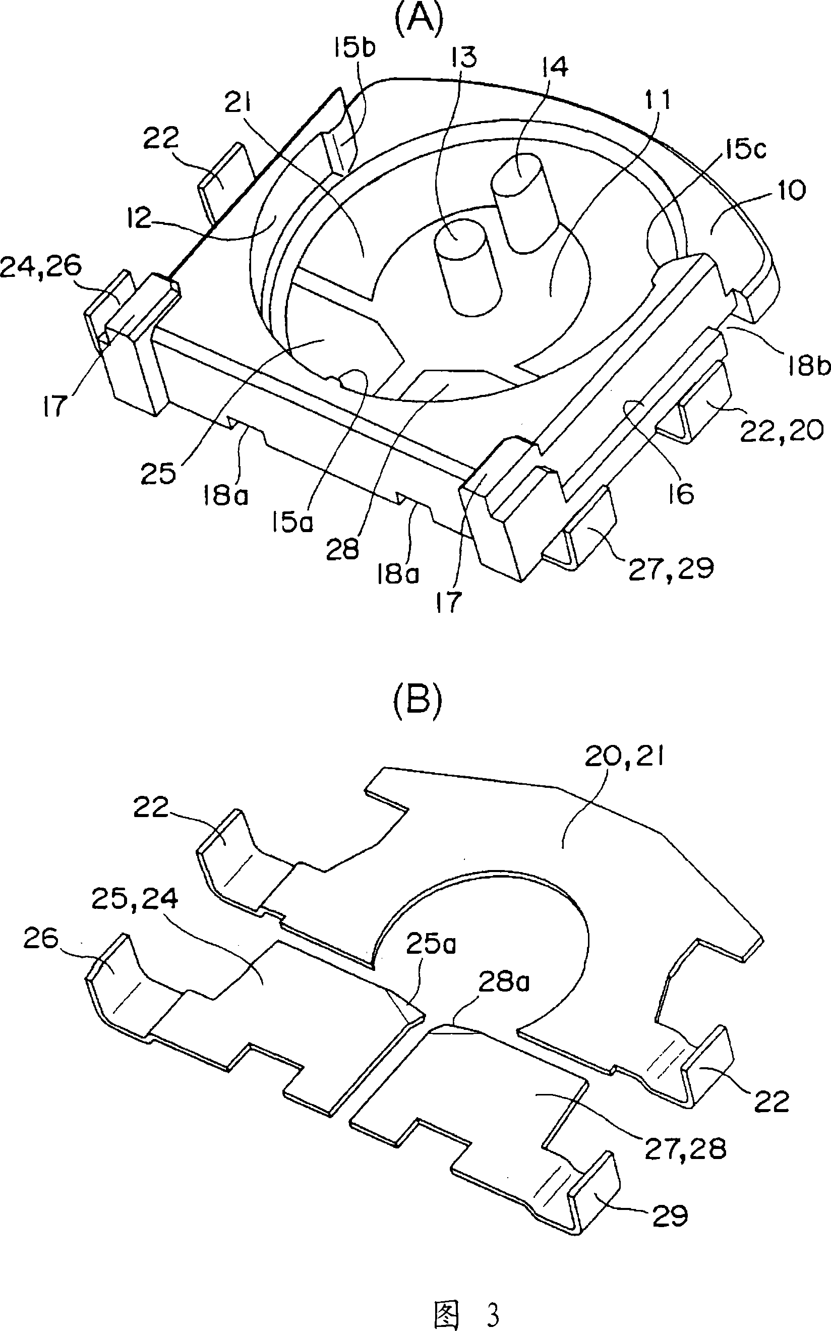
[0055] That is, as shown in FIG. 2 , the switch includes: a plane substantially square base 10, which is inserted and formed with a common fixed contact terminal 20 and a pair of switching fixed contact terminals 24, 27 on the bottom surface; , which is rotatably supported along the upper surface of the base 10; the movable contact piece 40, which is composed of a curved rod-shaped conductive spring member, is inserted into the fitting groove 34 of the operating rod 30 to be assembled; the coil spring 50, which presses the movable contact piece 40 to apply contact pressure; the cover 60, which covers the base 10, compresses the coil spring 50.

[0056] In addition, as an example of a product actually assembled, it has an overall height of 0.9 mm, a base...


PUM


Abstract

The present invention provides a low-cost switch which is made easily and saves noble metal. The switch includes a base (10), an operation lever (30), a movable contact piece (40), and a coil spring (50). In the base, fixed contact terminals (20, 24, 27) are insert-molded, and fixed contact portions (21, 25, 28) of the fixed contact terminals are exposed in a concentric manner to an upper surface. The operation lever is turnably supported along an upper surface of the base (10). The movable contact piece which is formed by a rod-shape conductive spring member, and the movable contact portions (41, 42) at both ends of the movable contact piece are slidably disposed to the fixed contact portions. The coil spring latches an arm portion (53) on one end side to the upper surface of the base (10) while latching an arm portion (53) on the other end side to the operation lever (30), the coil spring imparts a contact force and a returning force.

Description

technical field [0001] This invention relates to switches, particularly switches that are surface mounted on printed circuit boards or the like. Background technique [0002] Conventionally, as a switch that is surface-mounted on a printed circuit board or the like, there is a switch in which, for example, by rotating the rotary operating body 2, a special-shaped movable contact spring 4 that is formed by stamping an elastic metal sheet is rotated to make the contact spring 4 rotate. The contacts are turned on and off (for example, refer to Patent Document 1). [0003] Patent Document 1: (Japanese) Unexamined Patent Publication No. 2004-362979 [0004] However, the switch needs to manufacture the movable contact spring 4 having a complicated shape with high precision of parts, and the manufacturing process takes a lot of time. In addition, generally, the entire movable contact spring 4 having a large surface area needs to be plated with an expensive noble metal. Therefore...

Claims


Application Information

Patent Timeline
Patent Type & Authority Applications(China)
IPC IPC(8): H01H21/00H01H19/48
CPCH01H21/24H01H1/20H01H19/58
Inventor 清野泰弘鸣尾俊博
Owner ORMON CORP
Why Eureka
Try Eureka