Coaxial cable and manufacturing method thereof
A manufacturing method and coaxial cable technology, applied in the direction of cable/conductor manufacturing, flat/ribbon cable, two-part connection device, etc., can solve the problems of coaxial flat cable central conductor connection, insufficient fastening strength of cable 101, etc.
- Summary
- Abstract
- Description
- Claims
- Application Information
AI Technical Summary
Problems solved by technology
Method used
Image
Examples
no. 1 example
[0070] Hereinafter, embodiments of the present invention will be described in detail with reference to the accompanying drawings.
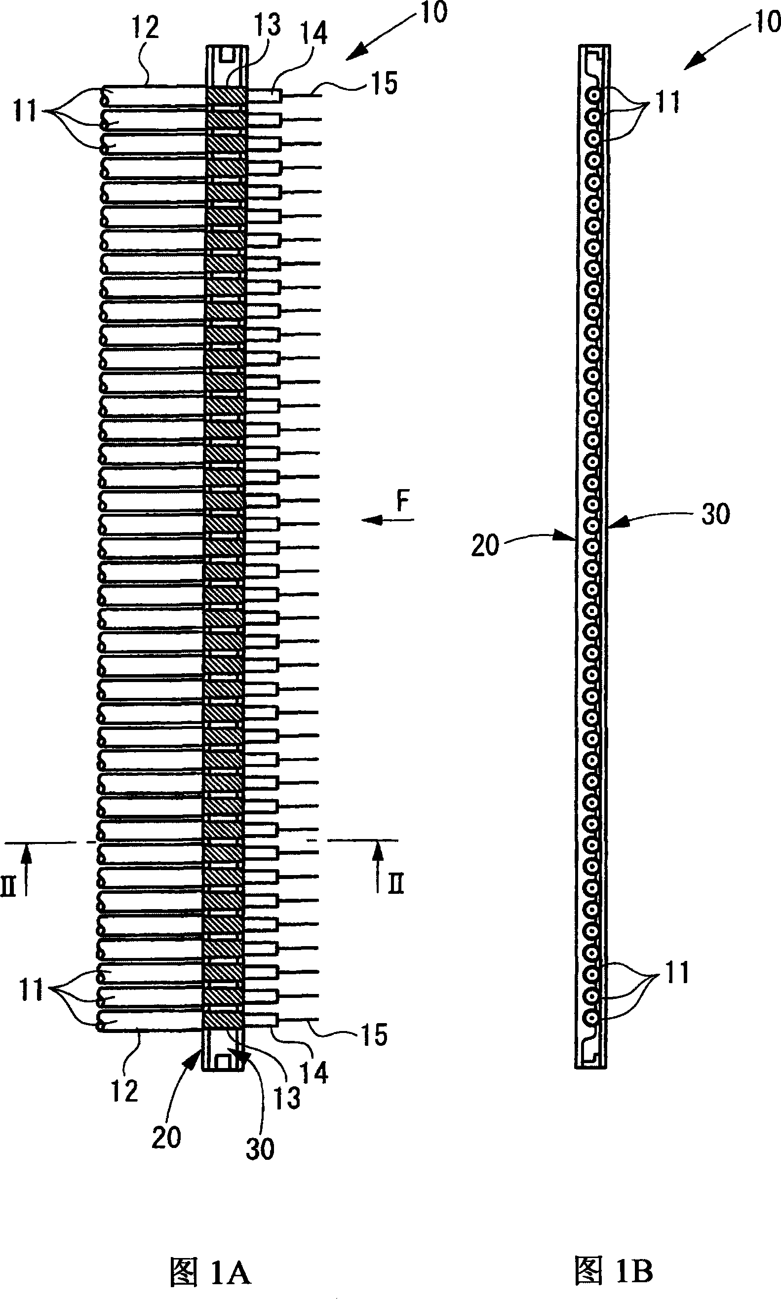
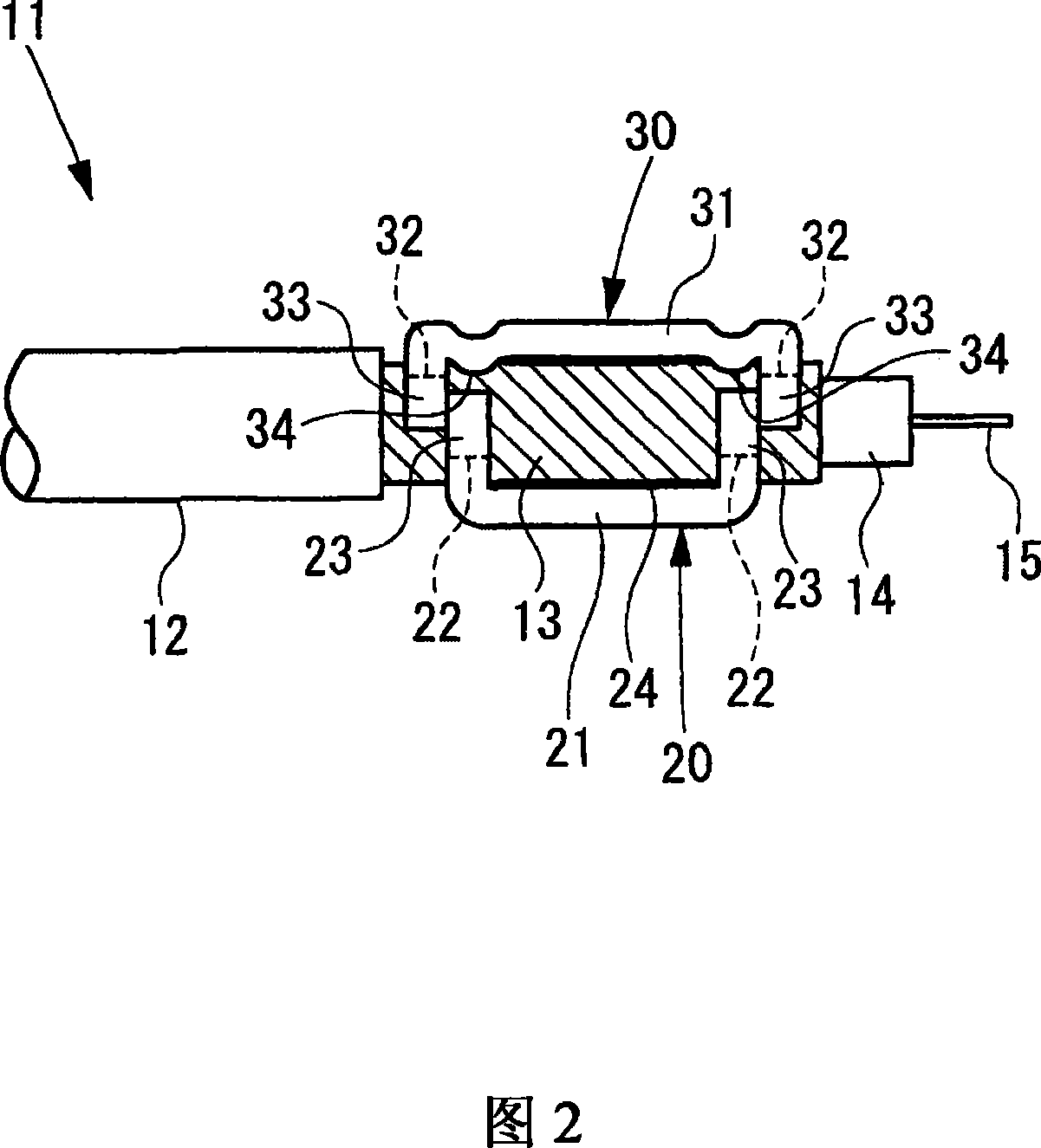
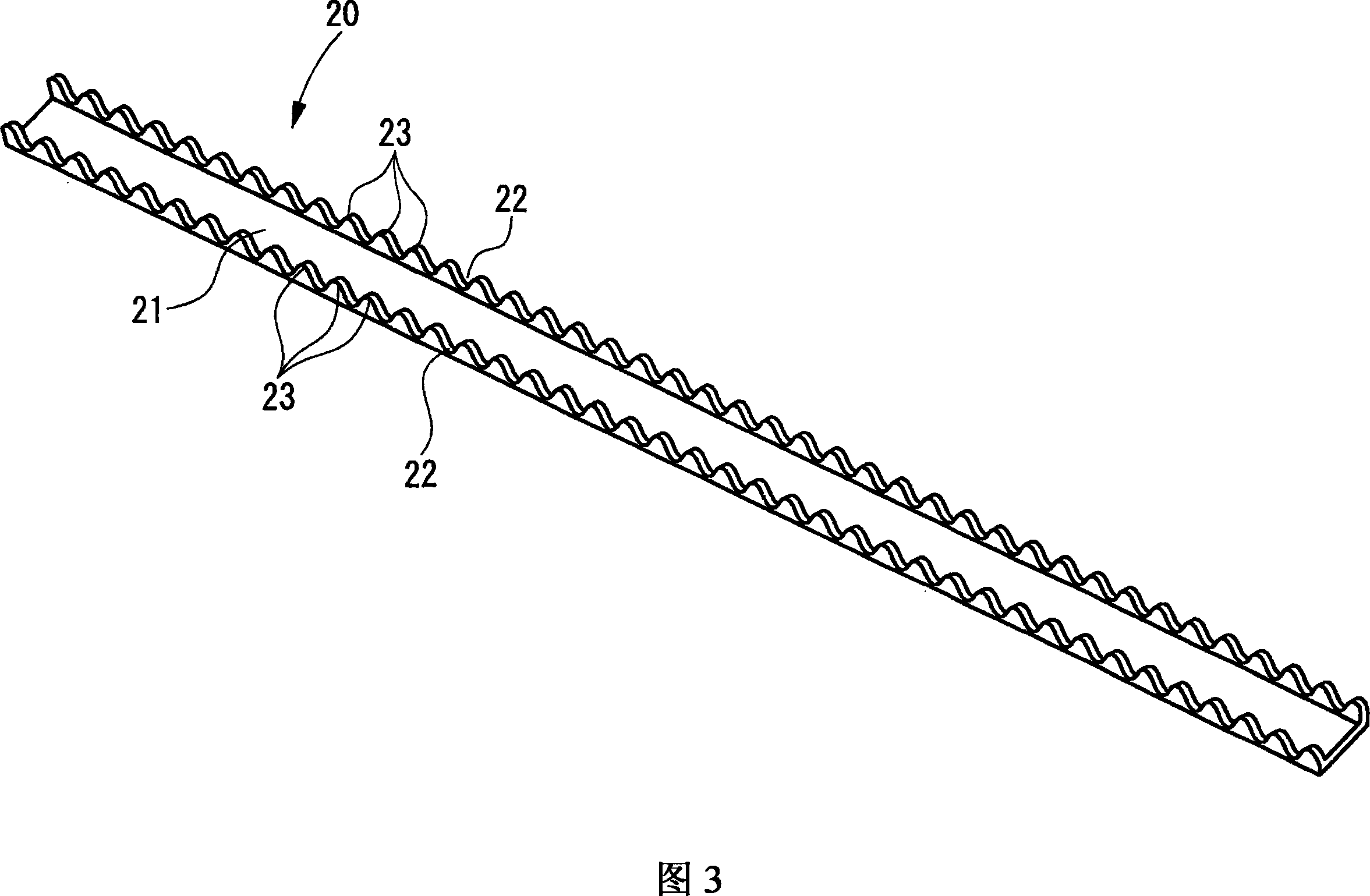
[0071] Fig. 1 shows a coaxial cable according to a first embodiment of the present invention. FIG. 1A is a plan view of the coaxial cable, and FIG. 1B is a side view seen from the direction F in FIG. 1A . FIG. 2 is a sectional view taken along line II-II in FIG. 1A and shows an end portion of a coaxial cable. Figure 3 is a perspective view of the ground rod with the ends removed. Fig. 4 is a perspective view of the pressing member with the ends removed. In FIG. 1A , the pressing member 30 (to be described below) is omitted to simplify the drawing.
[0072] As shown in FIG. 1, in the coaxial cable 10 according to the first embodiment of the present invention, a plurality of coaxial cables 11 are arranged in the horizontal direction. At the end portion of each coaxial cable 11 , the end portion of the outer sheath 12 is removed, and a part of th...
no. 2 example
[0098] FIG. 10A is a plan view of a coaxial flat cable according to a second embodiment of the present invention, and FIG. 10B is a side view seen in the direction of F in FIG. 10A . 11 is a cross-sectional view of an exemplary coaxial cable. 12A and 12B are cross-sectional views of an insulating covering member having a groove and a spacer, respectively. Fig. 13 is a plan view showing a state where the end portion of the center conductor is connected to the terminal.
[0099] As shown in FIGS. 10A and 10B , in a coaxial flat cable 210A according to a second embodiment of the present invention, a plurality of coaxial cables 211A are arranged in parallel to each other. Their ends are subjected to internal member exposing processing; that is, portions having predetermined lengths of center conductor 212A, insulator 213A, and outer conductor 214A of each coaxial cable 211A are sequentially exposed from the end side in a stepwise manner.
[0100] The exposed portions of the oute...
no. 3 example
[0113] Next, a coaxial flat cable according to a third embodiment of the present invention and its manufacturing method will be described.
[0114] Fig. 14 is a perspective view of a coaxial flat cable according to a third embodiment of the present invention. FIG. 15A is a plan view of the coaxial flat cable, and FIG. 15B is a cross-sectional view taken along line B-B in FIG. 15A . 16A to 16C are plan views and sectional views showing a method of manufacturing a coaxial flat cable according to a third embodiment of the present invention as process diagrams.
[0115] As shown in FIGS. 14 and 15, in a coaxial flat cable 210 according to a third embodiment of the present invention, at each end portion of a plurality of coaxial cables 211 arranged in parallel to each other, a center conductor 212, an insulator 213 Parts of the outer conductor 214 and the outer conductor 214 are sequentially exposed from the outer sheath 215 in a stepped manner. Ground rods 216 are provided which...
PUM
| Property | Measurement | Unit |
|---|---|---|
| Outer diameter | aaaaa | aaaaa |
Abstract
Description
Claims
Application Information
 - R&D
- Intellectual Property
- Life Sciences
- Materials
- Tech Scout
- Unparalleled Data Quality
- Higher Quality Content
- 60% Fewer Hallucinations
Browse by: Latest US Patents, China's latest patents, Technical Efficacy Thesaurus, Application Domain, Technology Topic, Popular Technical Reports.
© 2025 PatSnap. All rights reserved.Legal|Privacy policy|Modern Slavery Act Transparency Statement|Sitemap|About US| Contact US: help@patsnap.com


