Method for recovering tail gas generated by tetrafluoroethylene
A technology of tetrafluoroethylene and recycling methods, applied in separation methods, chemical instruments and methods, organic chemistry, etc., can solve problems such as increased operating costs, poor purity of recycled products, and increased environmental pollution
- Summary
- Abstract
- Description
- Claims
- Application Information
AI Technical Summary
Problems solved by technology
Method used
Image
Examples
Embodiment 1
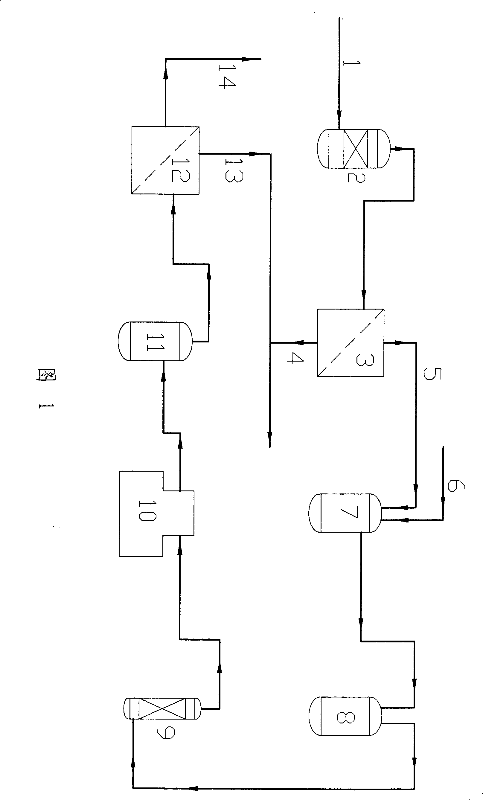
[0049] Embodiment 1: See Figure 1
[0050] Primary separation: TFE tail gas 1 temperature is -10°C, pressure is 1.1MPa(a), the molar weight composition of tail gas is TFE 83%, CO 17%, O 2 40ppm, enter the buffer tank 2 of the first-stage membrane inlet adsorber in gaseous state through the pipeline, and pass through the first-stage membrane separator 3 after the temperature is stabilized (about 2°C). The pressure difference between the two sides of the membrane module is 0.8MPa, and the gas residence time is 1.5 s, separated into permeate gas 5 with high CO content (the molar composition of the substance is CO 34%, TFE 66%, O 2 120ppm), introduced into the mixing tank 7 and CO through the pipeline 2 Gas 6 is mixed; Another stream is the retentate gas 4 of CO low content (the molar weight composition of material is TFE 89%, CO 11%, O 2 10ppm). The retentate gas 4 is decompressed and returned to the TFE compression recovery system.
[0051] Secondary separation: add CO in...
Embodiment 2
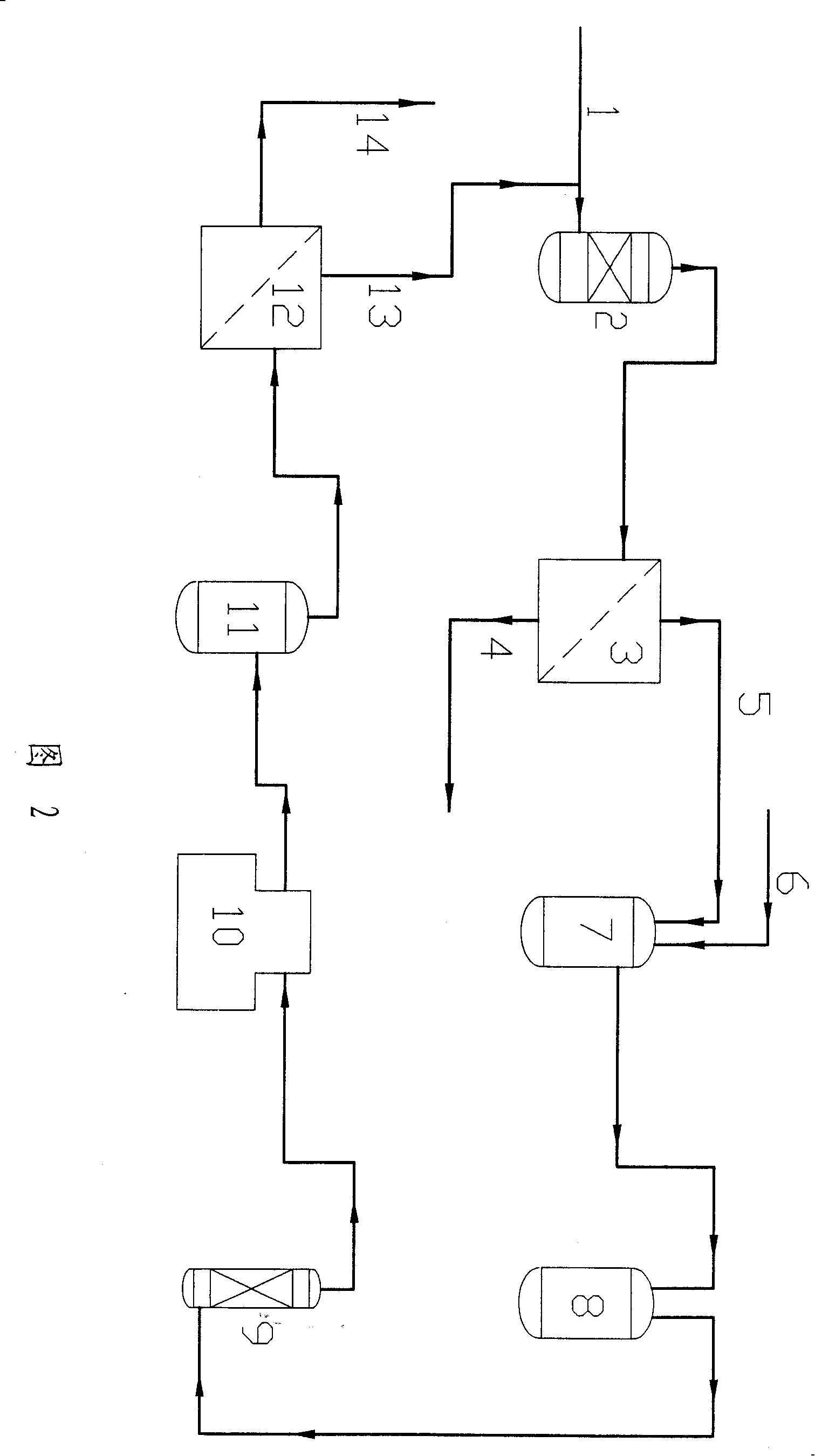
[0052] Example 2: See Figure 2
[0053] Primary separation: TFE tail gas 1 temperature is -10 ℃, pressure is 1.1MPa (absolute pressure), TFE tail gas 1 (the molar weight composition of substance is TFE 83%, CO 17%, O 2 40ppm) enters the buffer tank 2 of the primary membrane inlet adsorber in a gaseous state through the pipeline, and the retentate gas 13 of the secondary membrane separator 12 also enters the buffer tank 2 of the primary membrane inlet adsorber, and passes through the primary membrane separator 3 after the pressure is stabilized , the pressure difference on both sides of the membrane module is 0.9MPa, the gas residence time is 1.5s, and it is separated into permeate gas 5 with a high content of CO (the molar composition of the substance is 36.5% of CO, CO 2 2%, TFE 61.5%, O 2 110ppm), introduced into the mixing tank 7 with CO 2 Mixing; Another stream is retentate gas 4 with low content of CO (the molar weight composition of the substance is TFE 88%, CO 12%,...
Embodiment 3
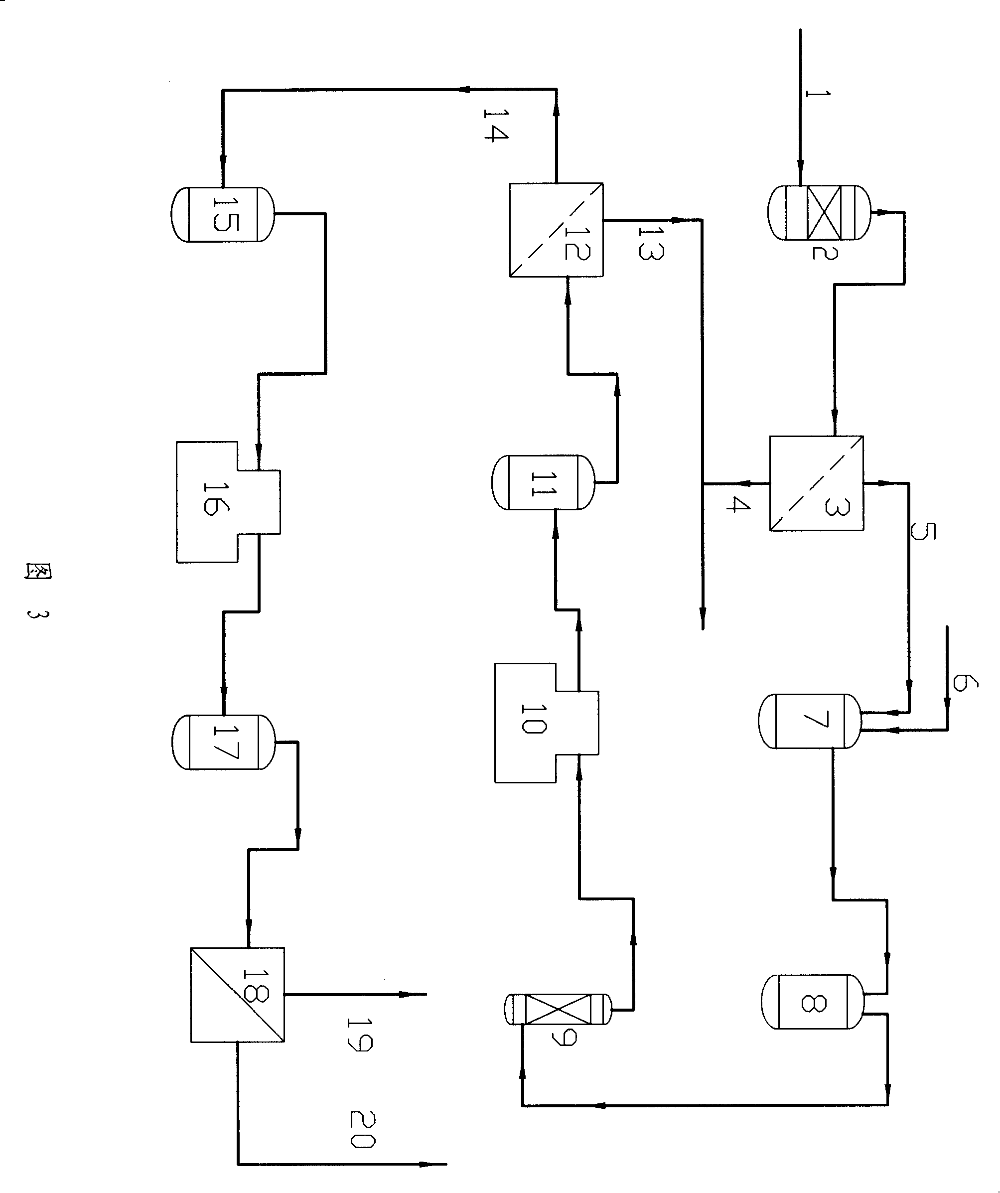
[0055] Embodiment 3: See Figure 3
[0056] Primary separation: TFE tail gas 1 temperature is -10°C, pressure is 1.1MPa(a), the molar weight composition of tail gas is TFE 83%, CO 17%, O 2 40ppm, enter the buffer tank 2 of the first-stage membrane inlet adsorber in gaseous state through the pipeline, and pass through the first-stage membrane separator 3 after the temperature is stabilized (about 2°C), the pressure difference between the two sides of the membrane module is 0.9MPa, and the gas residence time is 1.5 s, separated into permeate gas 5 with high CO content (the molar composition of the substance is CO 34%, TFE 66%, O 2 120ppm), introduced into the mixing tank 7 and CO through the pipeline 2 Gas 6 is mixed; Another stream is the retentate gas 4 of CO low content (the molar weight composition of material is TFE 89%, CO 11%, O 2 10ppm). The retentate gas 4 is decompressed and returned to the TFE compression recovery system.
[0057] Secondary separation: add CO in...
PUM
 Abstract
Description
Claims
Application Information
 - Generate Ideas
- Intellectual Property
- Life Sciences
- Materials
- Tech Scout
- Unparalleled Data Quality
- Higher Quality Content
- 60% Fewer Hallucinations
Browse by: Latest US Patents, China's latest patents, Technical Efficacy Thesaurus, Application Domain, Technology Topic, Popular Technical Reports.
© 2025 PatSnap. All rights reserved.Legal|Privacy policy|Modern Slavery Act Transparency Statement|Sitemap|About US| Contact US: help@patsnap.com


