Eureka AIR delivers breakthrough ideas for toughest innovation challenges, trusted by R&D personnel around the world.

Radio-frequency far end distributed system in radio communication system

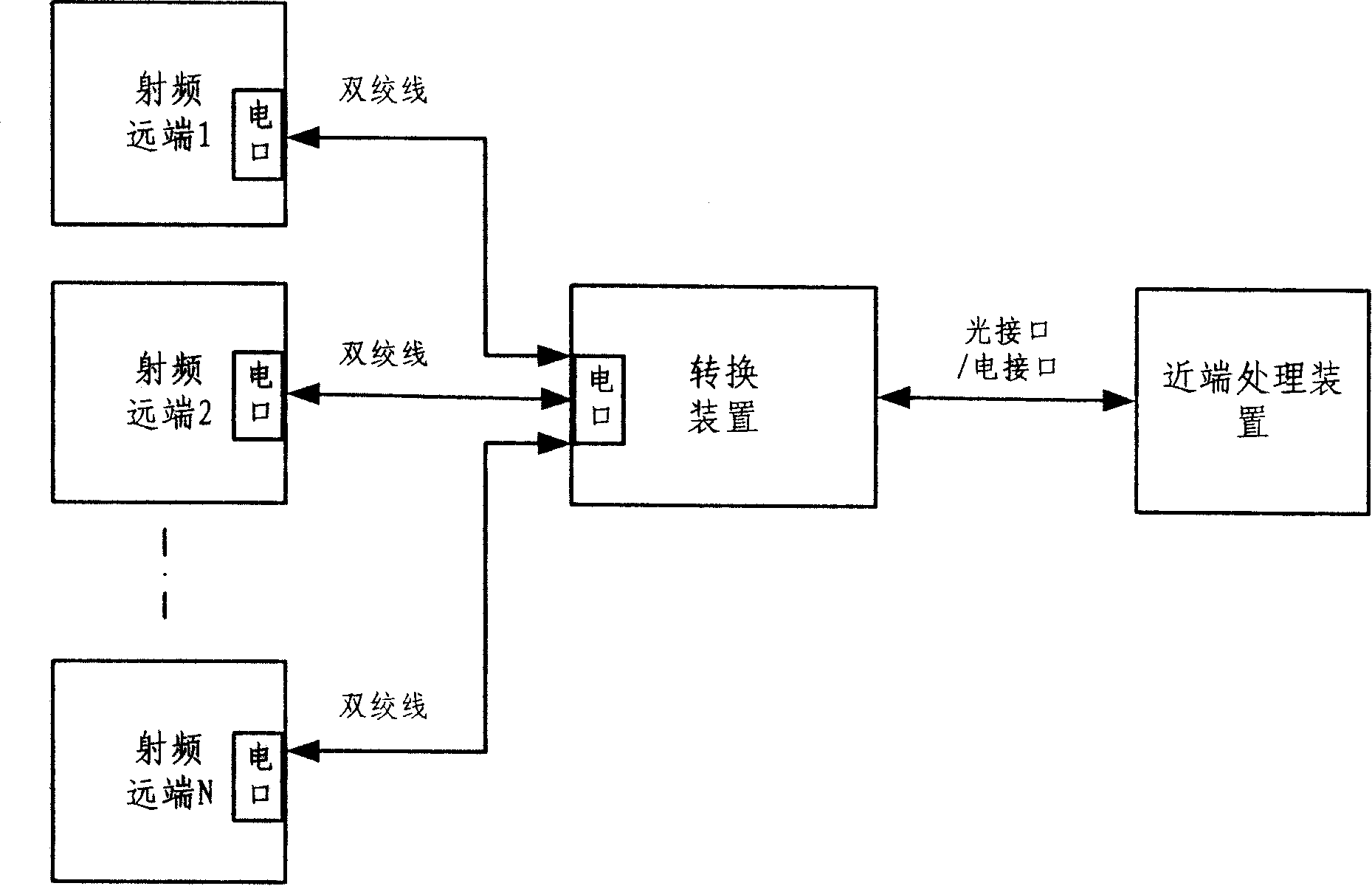
A wireless communication system, radio frequency remote technology, applied in the distribution system of radio frequency remote equipment, 2G, 3G distributed coverage network field, can solve the problems of high price of photoelectric converters, increase the time of network deployment, reduce the speed of network deployment, etc. Achieve the effect of saving laying time, shortening construction time and reducing construction volume

Inactive Publication Date: 2008-04-23
ZTE CORP
View PDF0 Cites 12 Cited by
  • Summary
  • Abstract
  • Description
  • Claims
  • Application Information

AI Technical Summary

Problems solved by technology

However, due to the relatively high price of photoelectric converters, when the number of RRU / remote units used is large, the total cost will be high
For an indoor distributed system, when multiple RRUs / remote units are used on each floor, it is necessary to increase the optical fiber wiring from the weak current well to the RRU / remote unit, which increases a certain amount of engineering, reduces the speed of network deployment, and increases netting time

Method used


Image

  • Radio-frequency far end distributed system in radio communication system
  • Radio-frequency far end distributed system in radio communication system
  • Radio-frequency far end distributed system in radio communication system

Examples


Embodiment Construction

[0023] The present invention will be further described in detail below in conjunction with the accompanying drawings and specific embodiments.

[0024] see figure 2 , which is the basic interface diagram of the present invention. For the radio frequency remote equipment at the antenna port, while completing the radio frequency processing and analog-to-digital conversion, the digital electrical signal is obtained according to a certain protocol and sent to the twisted pair. The electrical signal may be a high-speed electrical signal or a low-speed electrical signal, without limitation. After the conversion device receives the electrical signal sent from the twisted pair, it performs multiplexing / demultiplexing or digital combining / distribution processing on the signal, and then performs photoelectric conversion on the processed electrical signal according to a certain format, and will get The optical signal is sent to the near-end processing device unit through the optical f...


PUM


Abstract

This invention discloses a RF remote distribution system in the radio communication system including: at least one RF remote device connected with a converting device, which is connected with a near end process device, and the RF remote device and the converting device are intercommunicated by ordinary twisted-pair lines at low speed electric signals, and the converting device is used in finishing conversion of RF remote devices and near process devices and placed at a gathered place of five kinds of twisted-pair lines of RF remote devices or a position owning gathered interfaces of fiber and the twisted-pair lines at the same time since large amount of the interfaces are set in a building and the RF remote devices are placed at needed positions by the interfaces.

Description

technical field [0001] The invention relates to a radio frequency remote device distribution system, in particular to a distributed coverage network of 2G and 3G (second generation and third generation wireless communication systems) in the field of wireless communication. Background technique [0002] With the development of 3G technology, in order to solve the RF power loss caused by the feeder, there is a distributed solution of BBU (baseband pool) + RRU (radio remote unit). This solution usually connects the BBU and RRU through optical fibers. In addition, the repeater system currently also has a digital optical fiber repeater system, and the near-end unit and the far-end unit are also connected through optical fibers. The block diagrams of the two systems are attached figure 1 . However, due to the relatively high price of photoelectric converters, when the number of RRUs / remote units used is large, the total cost will be high. For an indoor distributed system, when...

Claims


Application Information

Patent Timeline
Patent Type & Authority Applications(China)
IPC IPC(8): H04B3/14H04B10/20H04B7/005
Inventor 廖娟周海涛
Owner ZTE CORP
Why Eureka
Eureka Blog
Learn More