Water-injected compressor

A compressor and water injection technology, applied in mechanical equipment, machines/engines, liquid variable volume machinery, etc., to prevent reproduction

Active Publication Date: 2008-04-23
HITACHI IND EQUIP SYST CO LTD
View PDF1 Cites 5 Cited by
  • Summary
  • Abstract
  • Description
  • Claims
  • Application Information

AI Technical Summary

Problems solved by technology

However, if the compressor part is stopped for too long, the water in the separator and piping that separates air and water will approach the atmospheric temperature, and microbes in the air may multiply in the water remaining in the separator or piping.

Method used


Image

  • Water-injected compressor
  • Water-injected compressor
  • Water-injected compressor

Examples


Embodiment Construction

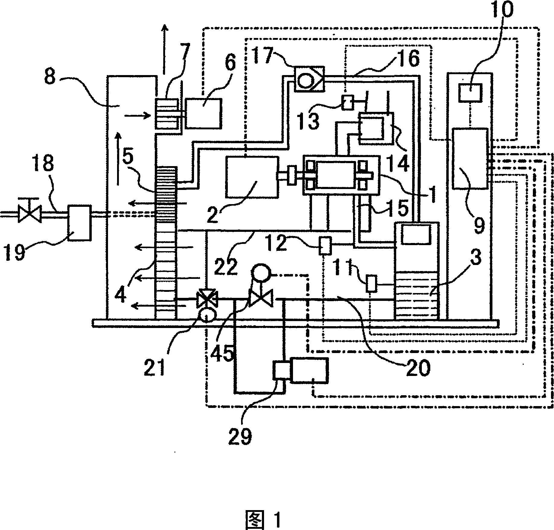
[0020] FIG. 1 shows a system configuration of a water jet compressor according to an embodiment. The compressor unit 1 is a positive displacement compressor, and a screw compressor will be described as an example.

[0021] The water in the separator 3 is supplied to the compressor 1 from the water supply pipe 20 connected to the separator 3 by the internal pressure of the separator 3 . The water cooled by the air-cooled water cooler 4 connected to the water supply pipe 20 is supplied from the water injection pipe 22 to the rotor working chamber of the compressor unit 1 . When the bearing of the compressor is a water-lubricated bearing, since there is no pressure to send out water in the separator 3 when the compressor unit 1 is started, the pump 29 installed between the water supply pipe 20 and the air-cooled water cooler 4 Start up, pressurize the water from the separator 3, and supply the water to the bearing of the compressor part 1.

[0022] The compressor part 1 compress...


PUM


Abstract

A water-jet compressor that does not require time-consuming work such as changing water until the next operation even if the compressor is stopped for a long time, and prevents the growth of microbes in the separator, compressor, and piping. The water injection compressor injects the water in the separator (3) into the compressor (1), and discharges it into the separator together with the compressed air for separation. Among them, after the compressor (1) is stopped, even after the preset When the compressor (1) is not started, the compressor (1) is also made to work for a specified time.

Description

technical field [0001] The present invention relates to a water injection compressor that injects water into a compressor and discharges the water together with compressed air. Background technique [0002] Water-jet compressors utilize water sprayed into the compressor section for lubrication and sealing. The water injection compressor has a water circulation system that circulates the water in order to re-inject the water discharged from the compressor into the compressor together with the compressed air. [0003] In the past, for example, Patent Document 1 describes that in order to reduce the impurity concentration of circulating water, continuous operation for a long time without supplying water, supply compressed air to the water tank, cool the compressed air leaving the water tank, and supply separated air to the compressor. After removing the moisture, drain the remaining circulating water from the sink. [0004] Patent Document 1: Japanese Patent Laid-Open No. 200...

Claims


Application Information

Patent Timeline
IPC IPC(8): F04B39/06
Inventor 武田文夫西村仁川端夏树青木优和
Owner HITACHI IND EQUIP SYST CO LTD
Why Eureka
Try Eureka