


Quick Research
Generate reliable direction feasibility study reports for your R&D in just a few steps.

Technical Q&A
Discover and master advanced knowledge NOW. Basics, ideas, possibilities, all at once.

Find Solutions
As an expert in R&D theories, this can generate solutions to your technical problems instantly.

Evaluate Feasibility
Analyze your overall solution with one click, know your potential R&D risks in advance.

Monitor Landscape
Get weekly tech updates, stay abreast of the latest tech innovations and key insights.
Fixing bed wet catalytic oxidation reactor using foamless oxygen-supplying technology
A wet catalytic oxidation, fixed bed technology, applied in chemical instruments and methods, oxidized water/sewage treatment, chemical/physical processes, etc., can solve the problem of low utilization rate of oxidants, achieve large surface area, speed up reaction speed, and increase surface area Effect
- Summary
- Abstract
- Description
- Claims
- Application Information
AI Technical Summary
Problems solved by technology
Method used
Image

Examples
specific Embodiment approach 1
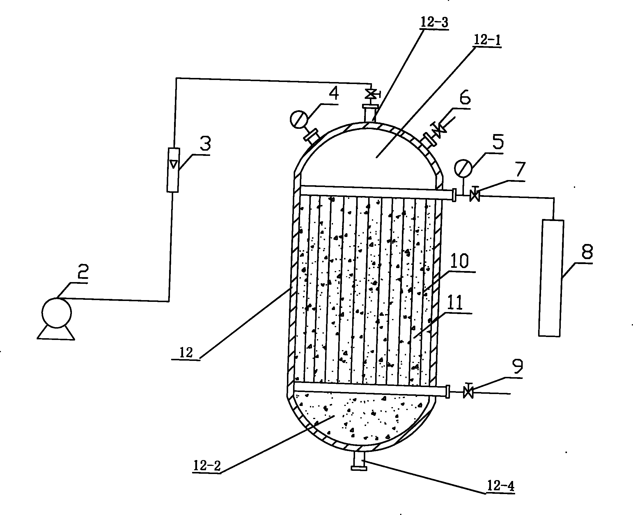
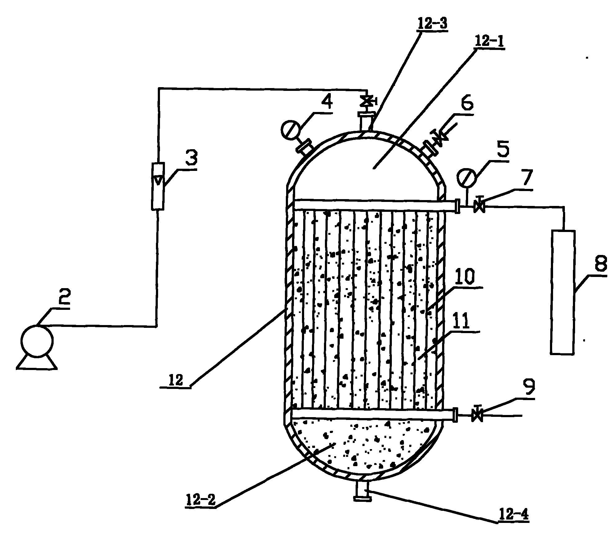
[0007] Specific implementation mode one: (see figure 1 ) This embodiment is composed of a housing 12, a hollow fiber membrane oxygen supply module 11 and an oxidant gas source 8. The hollow fiber membrane oxygen supply module 11 is longitudinally arranged in the housing 12 and divides the inner chamber of the housing 12 into an upper head chamber 12-1 and lower head chamber 12-2, the top of the upper head chamber 12-1 has a water inlet 12-3, the bottom of the lower head chamber 12-2 has a water outlet 12-4, and the hollow fiber The inlet pipe of the membrane oxygen supply assembly 11 passes through the housing 12 and communicates with the outlet of the oxidant gas source 8, the air outlet pipe of the hollow fiber membrane oxygen supply assembly 11 communicates with the outside of the housing 12, and the fiber of the hollow fiber membrane oxygen supply assembly 11 The catalyst particle packing is filled between the tubes 10, and the catalyst particle packing is one or more than...
specific Embodiment approach 2
[0013] Specific implementation mode two: (see figure 1 ) The difference between this embodiment and Embodiment 1 is that it also includes a liquid flow meter 3, a No. 1 pressure gauge 4, a No. 2 pressure gauge 5 and an exhaust valve 6, and the liquid flow meter 3 is arranged on the side of the water inlet 12-3. On the pipeline, the No. 1 pressure gauge 4 is set on the top of the housing 12 to measure the pressure in the upper head cavity 12-1, and the exhaust valve 6 is set on the top of the housing 12 to discharge the pressure in the upper head cavity 12-1. The No. 2 pressure gauge 5 is set between the inlet pipe of the hollow fiber membrane oxygen supply module 11 and the outlet of the oxidant gas source 8 . Such setting is beneficial to the monitoring and control of the reaction process of the reactor.
specific Embodiment approach 3
[0014] Embodiment 3: The difference between this embodiment and Embodiment 1 is that the oxidant gas source 8 is an oxidant gas bottle.
PUM
 Abstract
Description
Claims
Application Information
 - R&D Engineer
- R&D Manager
- IP Professional
- Industry Leading Data Capabilities
- Powerful AI technology
- Patent DNA Extraction
Browse by: Latest US Patents, China's latest patents, Technical Efficacy Thesaurus, Application Domain, Technology Topic, Popular Technical Reports.
© 2024 PatSnap. All rights reserved.Legal|Privacy policy|Modern Slavery Act Transparency Statement|Sitemap|About US| Contact US: help@patsnap.com