
Energy-saving control circuit

An energy-saving control and circuit technology, which is applied in the direction of circuit, electrical program control, sequence/logic controller program control, etc., can solve the problems of shortening the power supply time, not being able to extend it, and not being able to adjust the energy-saving circuit, so as to achieve low cost and high power consumption. Effects of reduced consumption and zero power consumption

Inactive Publication Date: 2008-04-16
SHENZHEN H&T INTELLIGENT CONTROL
View PDF0 Cites 7 Cited by
  • Summary
  • Abstract
  • Description
  • Claims
  • Application Information

AI Technical Summary

Problems solved by technology

[0004] However, traditional energy-saving circuits cannot be flexibly adjusted according to different loads or different needs. The power supply time is fixed, and the power supply time cannot be extended or shortened to make the load reach the most ideal working state.

Method used


Image

  • Energy-saving control circuit

Examples


Embodiment Construction

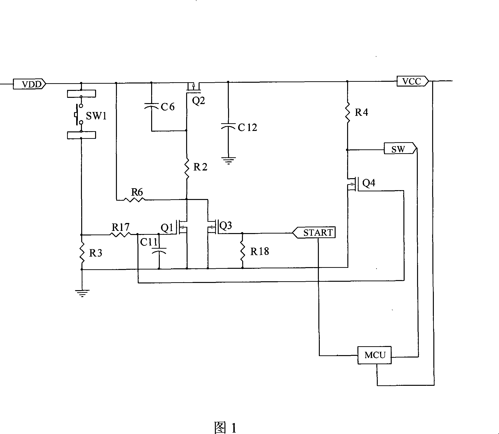
[0018] Please refer to FIG. 1 , the present invention relates to an energy-saving control circuit, which is used to save power consumption of a power-consuming device as a load. It includes power supply circuit and controller MCU.

[0019] The power supply circuit includes an access terminal VDD and a working terminal VCC.

[0020] Preferably, the energy-saving control circuit is suitable for battery-powered systems.

[0021] The working terminal VCC of the power supply circuit is connected to the controller MCU, and provides working power for the controller MCU.

[0022] A trigger circuit and a cut-off circuit are arranged between the access terminal VDD and the working terminal VCC.

[0023] Specifically, the trigger circuit includes a trigger switch SW1, a first P-channel FET switch Q1 and a second N-channel FET switch Q2 provided at the input terminal VDD and the working terminal VCC of the power supply circuit. The trigger switch SW1 is connected to the gate of the sec...


PUM


Abstract

The invention relates to an energy saving control circuit which is used for saving electricity consumption of a power consuming device. The invention comprises a power supply circuit and a controller, wherein, the power supply circuit comprises an incoming end and a working end. The working end of the power supply circuit is connected with the controller and supplies power for the controller, a trigger circuit and a cutoff circuit are arranged between the incoming end and the working end, the cutoff circuit is connected with the controller, the trigger circuit turns on the power supply circuit for supplying power for the power consuming device, and the controller cuts off the power supply circuit through the cutoff circuit. The energy saving control circuit of the invention can realize intelligent control on power output and save energy as much as possible when meeting the working requirements of different power consuming loads.

Description

technical field [0001] The invention relates to an energy-saving circuit, in particular to an intelligent node control circuit. Background technique [0002] In order to achieve the purpose of saving electricity in some power supply circuits, some energy-saving circuits are often used, such as alarms, time-delay lights, electronic code locks, etc. [0003] A traditional power saving circuit is generally provided with a trigger conduction circuit between the input terminal and the working terminal of the power supply circuit. The trigger-on circuit typically includes a manually operated switch. After the switch is pressed, the input end and the working end are turned on, so as to supply power to the power consumption equipment of the load. The switch generally has a short-term self-locking function. After the switch is pressed, the power supply circuit will continue to be turned on for a period of time until the switch jumps to cut off the power supply circuit. [0004] Ho...

Claims


Application Information

Patent Timeline
Patent Type & Authority Applications(China)
IPC IPC(8): G05B19/04H03K17/60
Inventor 徐天麒丁辉刘建伟首召兵
Owner SHENZHEN H&T INTELLIGENT CONTROL
Learn More