
Screw cap

A screw cap and cover plate technology, applied in the directions of capping, bottle/container caps, and capping containers tightly with caps, which can solve problems such as rainwater accumulation and dirt deposition.

Active Publication Date: 2008-04-16
SCHUETZ GMBH & CO KGAA
View PDF1 Cites 4 Cited by
  • Summary
  • Abstract
  • Description
  • Claims
  • Application Information

AI Technical Summary

Problems solved by technology

[0002] Disadvantages of the screw caps disclosed by EP0650446 B1 for closing the injection nozzles of plastic liners of bung barrels or tray containers with grid or sheet shells are that dirt deposits on the cap surface, and When the container is left out in the open, rainwater collects in the basin-shaped recess of the cover pan that accepts the bung nipple

Method used


Image

  • Screw cap
  • Screw cap
  • Screw cap

Examples


Embodiment Construction

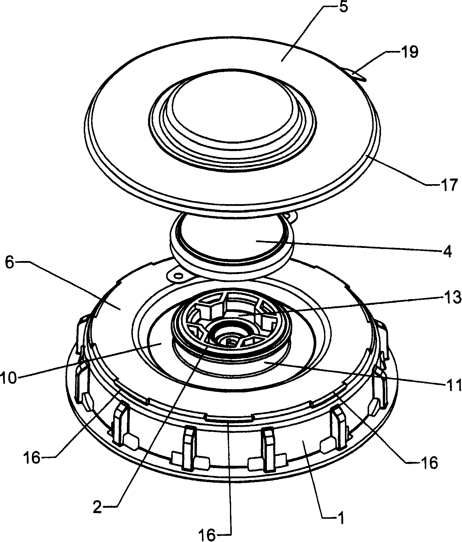
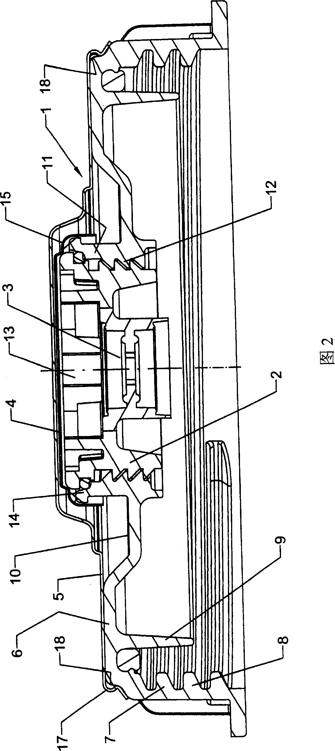
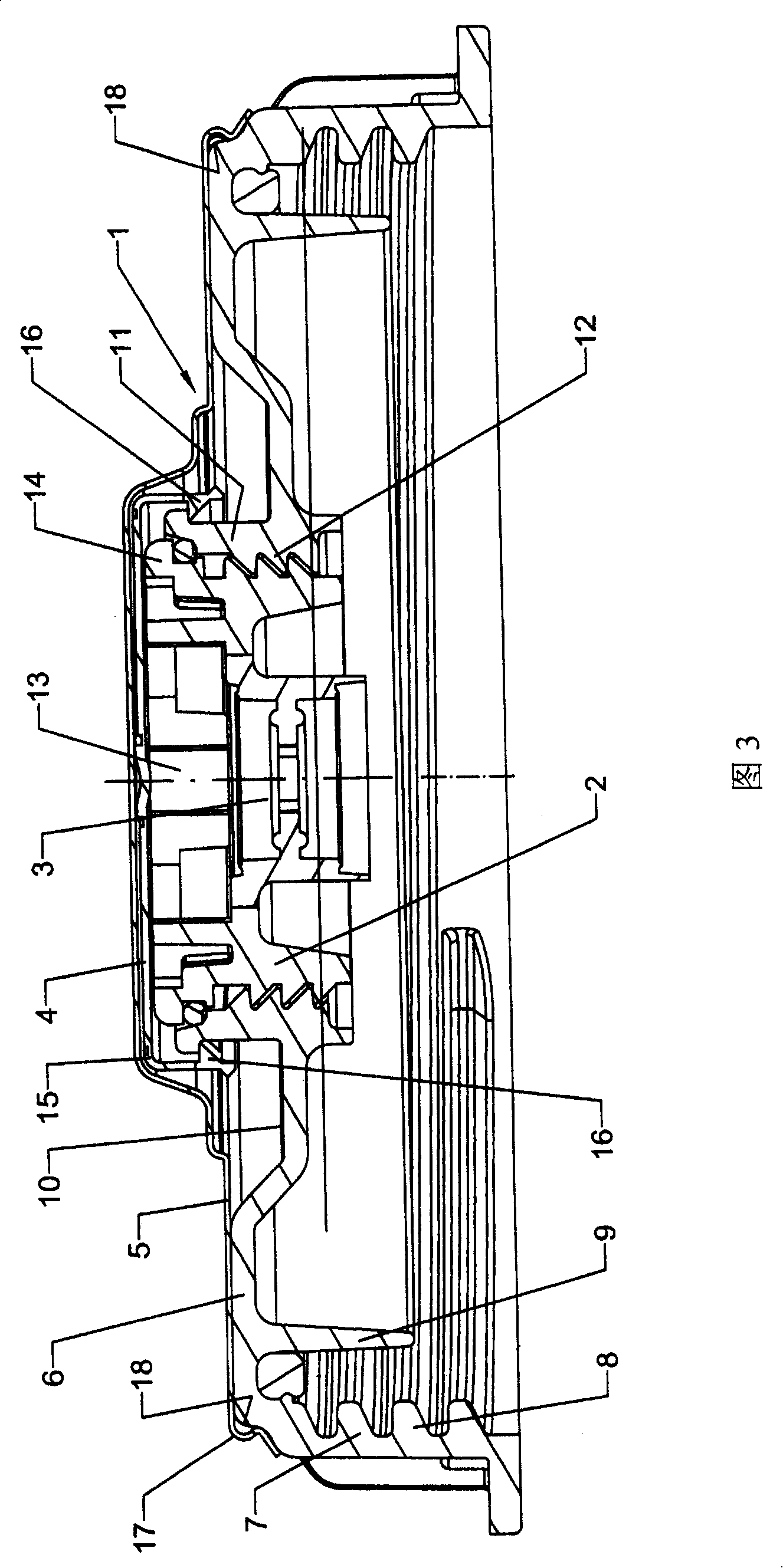
[0011] The plastic screw cap 1 is equipped with a bung 2 integrally integrated with a venting-and-inflating device, a sealing cap 4 and a protective cap 5 completely covering the screw cap 1 .

[0012] The screw cap 1 comprises a flat cover plate 6, which is vertically attached to an outer cover edge 7 and an inner cover edge 9 at the circumference of the cover plate, wherein the outer cover edge has an internal thread 8 to close the filling nozzle of the liquid storage and transportation container and / or The extraction nozzle, while the inner lid edge 9 is arranged in the center of the outer lid edge 7 and serves to reinforce and improve the placement of the screw cap on the filling and / or removal nozzle of the container.

[0013] In the central basin-shaped recess 10 of the cover plate 6 of the screw cap 1, a bung connecting pipe 11 is sunk. Insufficient pressure in the vent and inflator bung 2. The bung 2 has an upper engagement opening 13 adapted to a bung key for screwin...


PUM


Abstract

The plastic screw cap (1) that closes the injection and / or discharge connection of the liquid storage and transportation container is equipped with a bung (2) integrally combined with a venting and inflation device (3), a sealing cap (4) and a screw cap ( 1) Protective cover (5) that covers completely and prevents contamination.

Description

technical field [0001] The invention relates to a screw cap with a cover plate, a cover rim attached vertically to the circumference of the cover plate, a bung adapter (Spundstutzen) and a sealing cap covering the bung (Spundstopfen), wherein the cover rim has Internal thread to close the injection and / or extraction connection of the liquid storage and transportation container; bung for device or vent / inflate device. Background technique [0002] Disadvantages of the screw caps disclosed by EP0650446 B1 for closing the injection nozzles of plastic liners of bung barrels or tray containers with grid or sheet shells are that dirt deposits on the cap surface, and When the container is left in the open, rainwater collects in the basin-shaped recess of the cover plate for receiving the bung nipple. Contents of the invention [0003] The object of the present invention is to improve screw caps of this type from the point of view of avoiding the deposition of dirt on the cap su...

Claims


Application Information

Patent Timeline
Patent Type & Authority Applications(China)
IPC IPC(8): B65D41/04B65D47/06B65D41/62
CPCB65D47/121B65D51/18
Inventor 发明人请求不公布姓名
Owner SCHUETZ GMBH & CO KGAA
Learn More