
Liquid crystal display device

A technology of liquid crystal display device and liquid crystal layer, which can be used in static indicators, nonlinear optics, instruments, etc., and can solve the problem of white display tone difference

Active Publication Date: 2008-04-09
JAPAN DISPLAY INC
View PDF1 Cites 1 Cited by
  • Summary
  • Abstract
  • Description
  • Claims
  • Application Information

AI Technical Summary

Problems solved by technology

[0019] Moreover, regarding the above-mentioned inconvenience, when an isotropic liquid crystal is used as the liquid crystal, there is no influence caused by the scattering of the liquid crystal in the black display, and the scattering caused by the color filter becomes the main cause, and the black display has a great influence on the liquid crystal. The difference in the hue of the white display becomes more conspicuous

Method used


Image

  • Liquid crystal display device
  • Liquid crystal display device
  • Liquid crystal display device

Examples


Embodiment Construction

[0092] Embodiments of the liquid crystal display device of the present invention will be described below using the drawings.

[0093]

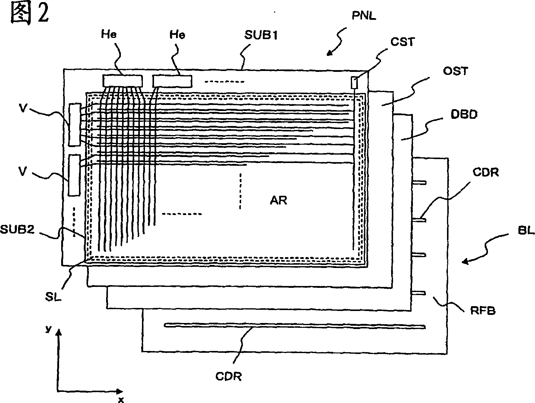
[0094] FIG. 2 is a perspective view schematically showing the whole of the liquid crystal display device of the present invention. In the figure, the liquid crystal display device is configured by arranging a liquid crystal display panel PNL, an optical sheet OST, a diffusion plate DBD, and a backlight BL in this order from the viewer side.

[0095] The liquid crystal display panel PNL is configured as a peripheral by a pair of transparent substrates SUB1 and SUB2 in which liquid crystal is interposed. The transparent substrate SUB2 is formed to be slightly smaller in area than the transparent substrate SUB1, and the transparent substrate SUB1 is exposed such as the left edge and the upper edge in the figure, and is arranged to face the transparent substrate SUB2. The scanning signal drive circuit V composed of a plurality of flip-chip semi...


PUM


Abstract

PROBLEM TO BE SOLVED: To provide a liquid crystal display whose visual field angle characteristics are further enhanced, despite the liquid crystal display having a simple and inexpensive constitution. ŽSOLUTION: The liquid crystal display includes a first substrate, a second substrate, polarizing plates provided to the first substrate and the second substrate, a liquid crystal layer, disposed between the first substrate and the second substrate, a first electrode provided to the first substrate and a second electrode applying an electric field to the liquid crystal layer by the potential difference generated between the first and the second electrodes, the liquid crystal layer has properties where the optical anisotropy is generated by voltage application from optically isotropic state, and the polarizing plate is constituted of an E (extraordinary)-type polarizer. Ž

Description

technical field [0001] The present invention relates to a liquid crystal display device, and particularly to a so-called transverse electric field type liquid crystal display device. Background technique [0002] When a liquid crystal display device is used as a television or a monitor, it is desired that the liquid crystal display device has good so-called wide viewing angle characteristics. [0003] In this case, when comparing a liquid crystal display device called a transverse electric field method with, for example, a conventional twisted nematic (TN) method, a larger viewing angle characteristic can be obtained. [0004] This is because a transverse electric field type liquid crystal display device has a pair of electrodes in each pixel region on the surface of the liquid crystal layer of one of the opposing substrates with the liquid crystal layer interposed therebetween. The behavior of the liquid crystal molecules corresponding to the electric field generated by th...

Claims


Application Information

Patent Timeline
IPC IPC(8): G02F1/1335G02F1/1333G02F1/1362G02F1/133G09G3/36
Inventor 内海夕香桧山郁夫梶田大介小野记久雄
Owner JAPAN DISPLAY INC
Learn More