Variable valve for internal combustion engine

一种内燃机、气门的技术,应用在阀装置、机械设备、发动机元件等方向,能够解决电力供给量不足、无法控制轴移动、发动机性能提高程度下降等问题,达到降低燃料费用的效果

Active Publication Date: 2008-04-09
NISSAN MOTOR CO LTD
View PDF1 Cites 5 Cited by
  • Summary
  • Abstract
  • Description
  • Claims
  • Application Information

AI Technical Summary

Problems solved by technology

However, since electric power needs to be supplied to the starter motor when the engine is started, the amount of electric power supplied to the motor, which is the driver of the variable valve device, is insufficient, and the control shaft cannot be quickly moved to a rotational angle position suitable for starting.
Therefore, it is necessary to set the lift and operating angle suitable for starting during idling operation. Since the use area to the small lift and small operating angle side is limited, the degree of improvement in engine performance such as fuel consumption is significantly reduced.

Method used


Image

  • Variable valve for internal combustion engine
  • Variable valve for internal combustion engine
  • Variable valve for internal combustion engine

Examples


Embodiment Construction

[0029] An embodiment of the present invention will be described in detail below with reference to the accompanying drawings.

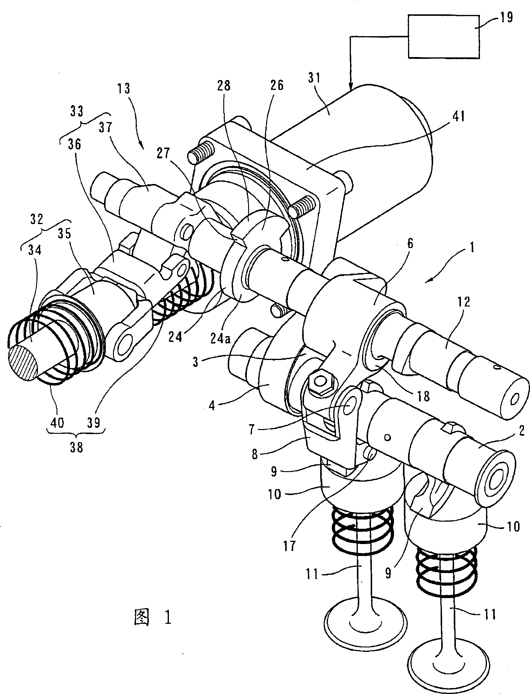
[0030] FIG. 1 is a perspective view schematically showing a variable valve device 1 of an internal combustion engine. This variable valve device 1 represents a mechanism that drives the intake valve 11 to open and close mechanically in conjunction with the rotation of the crankshaft (not shown), and that drives the intake valve 11 with the rotation of the control shaft 12 . Specifically, the lift characteristic of the valve 11 is a lift operating angle variable mechanism that continuously changes both the valve lift and the operating angle of the intake valve 11 . Since this variable valve device 1 is known from, for example, the above-mentioned Patent Document 1, etc., only an outline thereof will be described.

[0031] The variable valve device 1 includes: a drive shaft 2, which is freely rotatably supported on a cam bracket (not shown) on the upper...


PUM


Abstract

The present invention relates to a variable valve device of the internal combustion engine, which can enlarge the lift range character of the variable valve device to a variable range. The electric driver (13) comprises the following components: an electric motor (31), a ball screw device (32) connected to the electric motor (31), and a link device (33) which connected between the ball screw device (32) and the control shaft (12), and the rotary force of the electric motor (31) is transferred to the control shaft (12) through the ball screw device (32) and the link device (33). The ball screw device (32) comprises the following components: a ball screw (34) driven by the electric motor (31), and a ball nut (35) which does not rotate itself and retreats on the ball screw (34) by the rotating of the ball screw (34). The ball nut (35) functions by the clamping of the spring components (39 and 40). Thereby, the control shaft (12) can be kept at the middle position between the upper limit position and the lower limit position.

Description

technical field [0001] The present invention relates to a variable valve device for an internal combustion engine. Background technique [0002] The currently known variable valve device is linked with the crankshaft of the internal combustion engine to open and close the intake valve or exhaust valve, and changes the lift of the intake valve or exhaust valve as the control shaft rotates. engineering characteristics. [0003] Patent Document 1 discloses that such a variable valve device is provided with a stopper mechanism that mechanically limits the upper limit position and lower limit position of the rotatable range of the control shaft, and sets the control target value of the control shaft to Set to a range smaller than the rotatable range defined by the stopper mechanism. [0004] In this patent document 1, the stopper mechanism generally includes: a minimum operating angle side stopper and a maximum operating angle side stopper extending from the driver plate fixed ...

Claims


Application Information

Patent Timeline
Patent Type & Authority Applications(China)
IPC IPC(8): F01L1/00F01L13/00F02D13/02
CPCF01L13/0026F01L13/0021F01L2013/0073F01L2001/0476F01L2820/032
Inventor 赤坂裕三
Owner NISSAN MOTOR CO LTD
Why Eureka
Try Eureka