
Optical element and method for recording beam parameters, comprising a temperature sensor provided in the form of a pixel matrix

A technology of temperature sensor and optical element, applied in the field of optical element

Active Publication Date: 2010-09-01
TRUMPF WERKZEUGMASCHINEN GMBH & CO KG
View PDF9 Cites 0 Cited by
  • Summary
  • Abstract
  • Description
  • Claims
  • Application Information

AI Technical Summary

Problems solved by technology

However, said temperature change can only be registered collectively over the length of each conductor track or its two ends
Therefore, the evaluation of the beam state and beam size can only be made approximately

Method used


Image

  • Optical element and method for recording beam parameters, comprising a temperature sensor provided in the form of a pixel matrix
  • Optical element and method for recording beam parameters, comprising a temperature sensor provided in the form of a pixel matrix
  • Optical element and method for recording beam parameters, comprising a temperature sensor provided in the form of a pixel matrix

Examples


Embodiment Construction

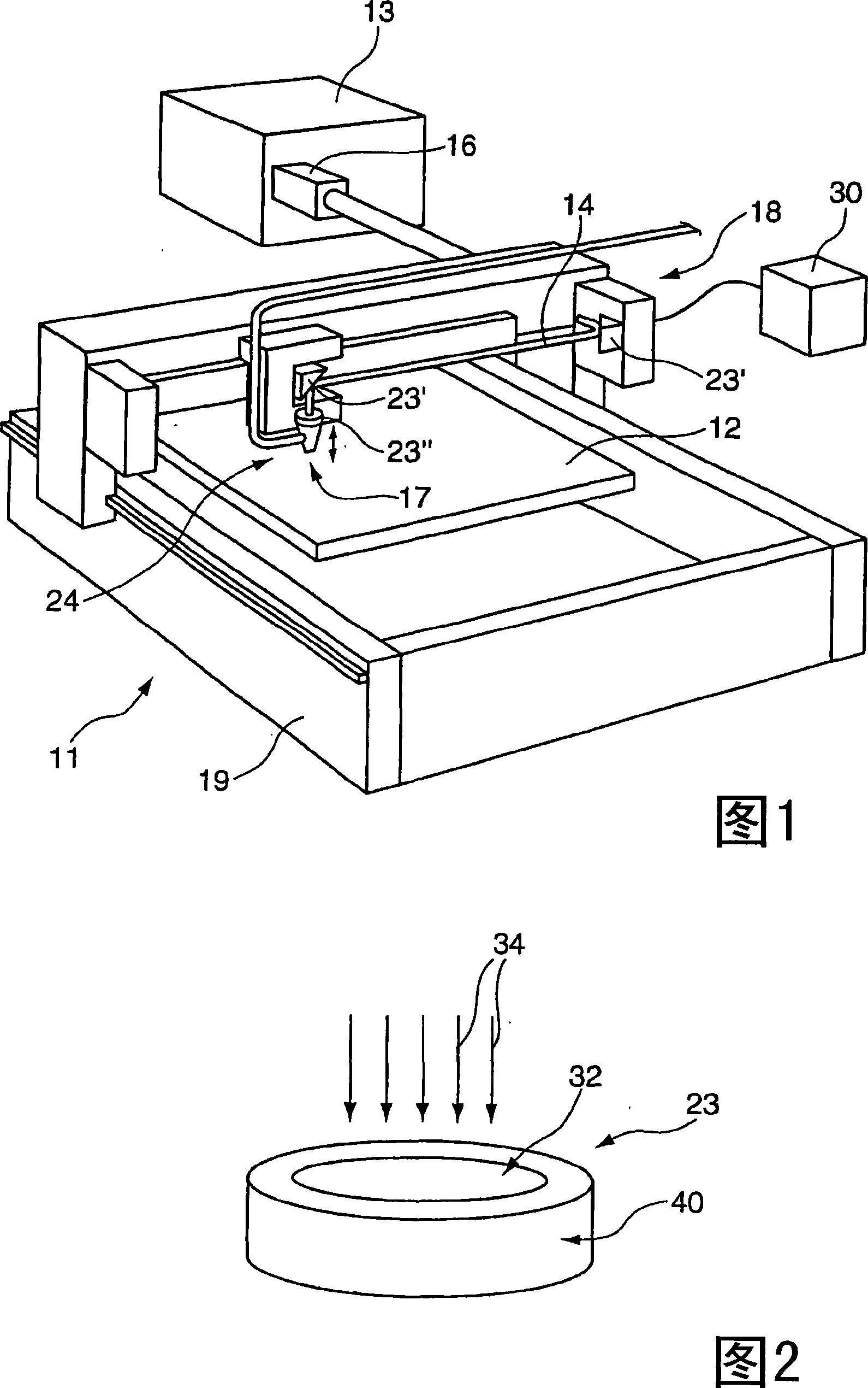
[0037] exist figure 1 A laser system 11 is shown, for example a laser system for processing materials and workpieces 12 . The laser system 11 includes a laser device 13, especially a CO 2 A laser device of a laser that generates electromagnetic radiation, in particular a laser beam 14 . The wavelength of the laser beam 14 is preferably in the far infrared range. A beam telescope 16 is arranged on the laser device 13 via which the laser beam 14 generated in the laser device 13 is coupled out. Laser beam 14 is guided from beam telescope 16 to processing location 17 via external optical unit 18 . The external optical unit 18 is arranged on a machine base 19, which is designed to be single-axis or multi-axis according to the application. In this exemplary embodiment, the external optical unit 18 moves in X, Y and Z directions. Single-axis or multi-axis optical units are also referred to as floating optical units. Alternatively, the workpiece 12 and / or the optical unit 18 can...


PUM

PropertyMeasurementUnit
reflectanceaaaaaaaaaa
transmittivityaaaaaaaaaa

Abstract

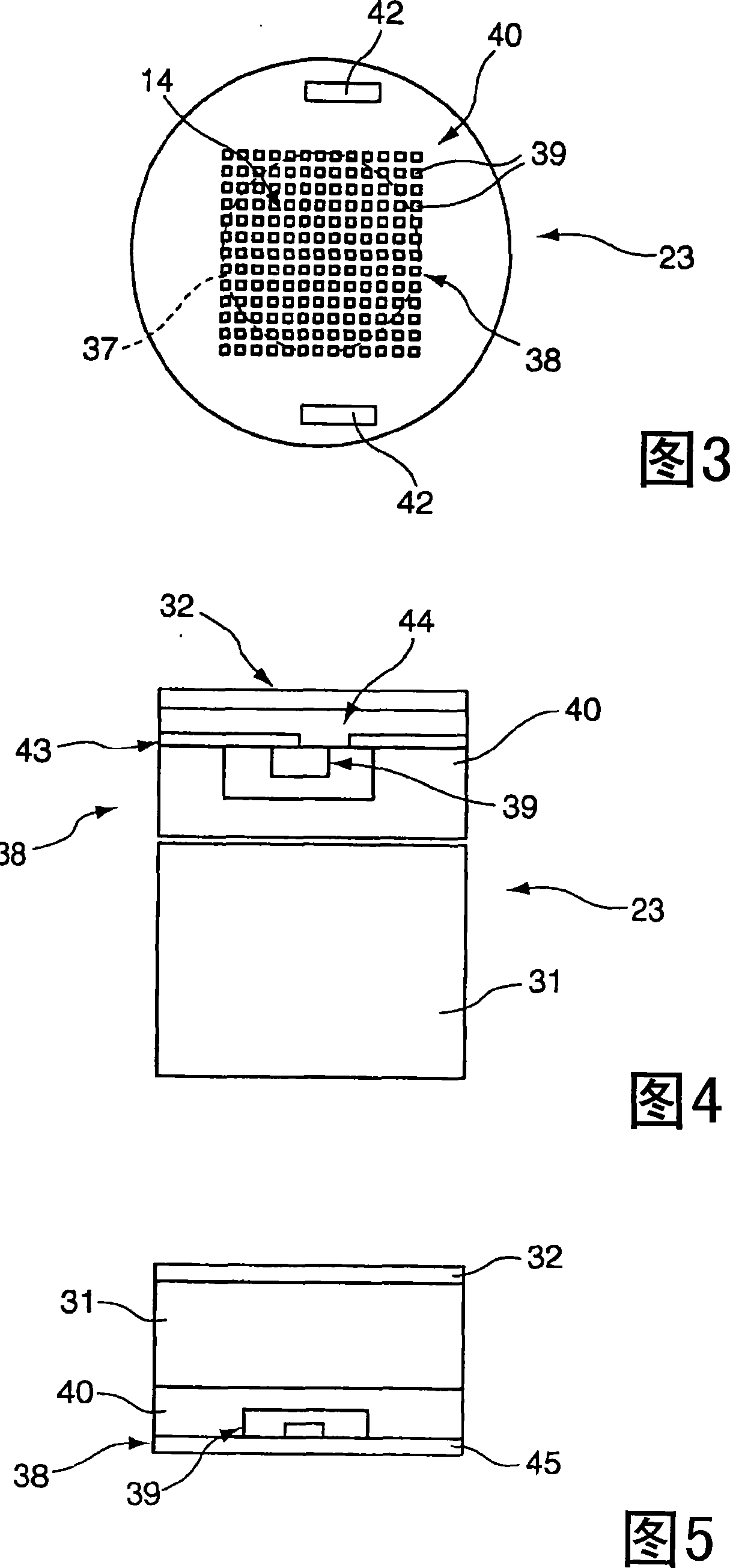
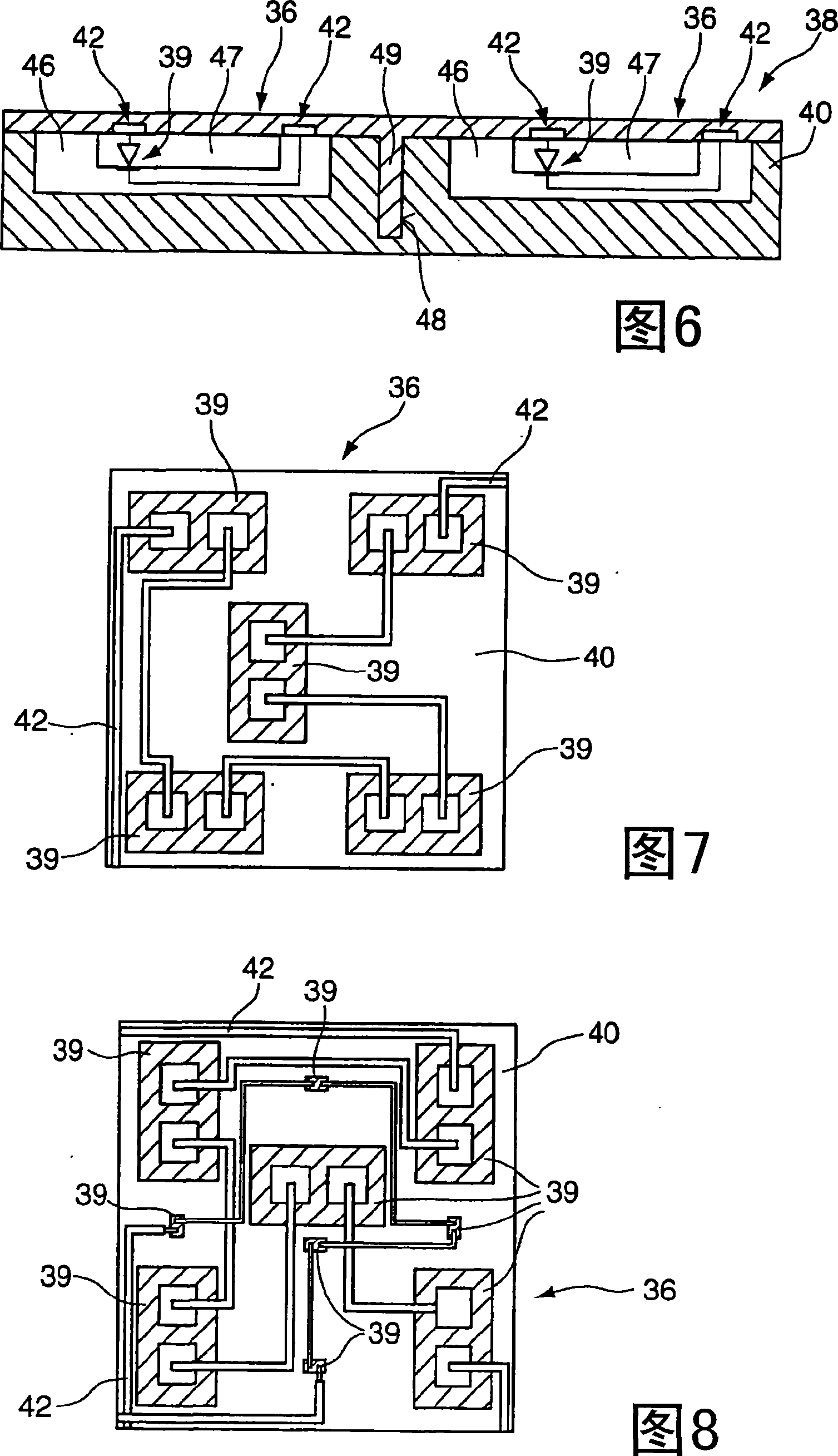
The invention relates to an optical element for guiding and forming a laser beam, and to a method for recording beam parameters, particularly in a laser system, comprising a carrier substrate (40) and a coating (39), which is applied to at least one side of the carrier substrate (40), and comprising at least one temperature sensor (38). The temperature sensor (38) is comprised of a number of pixels arranged in a matrix, and each respective pixel has at least one temperature-sensitive element (39). The at least one temperature-sensitive element (39) of the pixel is constructed inside the carrier substrate (40) made of silicon.

Description

technical field [0001] The invention relates to an optical element for guiding and shaping a laser beam according to the preamble of claim 1 and to a method for recording beam parameters with such an optical element according to the preamble of claim 14 . Background technique [0002] In industrial manufacturing, the use of laser beams to process materials is widespread. For process monitoring and for quality assurance, laser devices are required to generate a constant electromagnetic radiation power and to output this power with constant parameters. A plurality of optical elements are arranged in the laser system by means of which the beam is guided and shaped. At the same time, the power of the beam is thus also affected. The quality of a laser system is primarily determined by the beam orientation, beam profile and beam power. These parameters are optimized for the process and can be adversely affected by aging of the optics, incipient destruction and / or contamination ...

Claims


Application Information

Patent Timeline
Patent Type & Authority Patents(China)
IPC IPC(8): B23K26/42G01K17/00G01K11/00H01L27/146
CPCG01K17/003H01L27/146B23K26/422B23K26/702
Inventor J-M·魏克A·霍恩G·哈曼P·莱滕贝格尔N·科利尔R·P·约内斯
Owner TRUMPF WERKZEUGMASCHINEN GMBH & CO KG
Learn More