
Optical element array, display device, and method of manufacturing display device, optical element array and optical element array molding die

A technology for optical components and display devices, applied in the direction of optical components, optical components, optics, etc., can solve problems such as large size, and achieve the effect that is conducive to the installation of high-precision lenses

Active Publication Date: 2008-03-19
NEC LCD TECH CORP
View PDF1 Cites 19 Cited by
  • Summary
  • Abstract
  • Description
  • Claims
  • Application Information

AI Technical Summary

Problems solved by technology

When the known art method of arranging linear fiducial marks on the display screen is applied to this display screen, measures such as arranging fiducial marks on the outside of the drive circuit are required, so the size becomes very large

Method used


Image

  • Optical element array, display device, and method of manufacturing display device, optical element array and optical element array molding die
  • Optical element array, display device, and method of manufacturing display device, optical element array and optical element array molding die
  • Optical element array, display device, and method of manufacturing display device, optical element array and optical element array molding die

Examples


Embodiment Construction

[0064] Exemplary embodiments of the present invention will now be described with reference to the accompanying drawings.

[0065] (first exemplary embodiment)

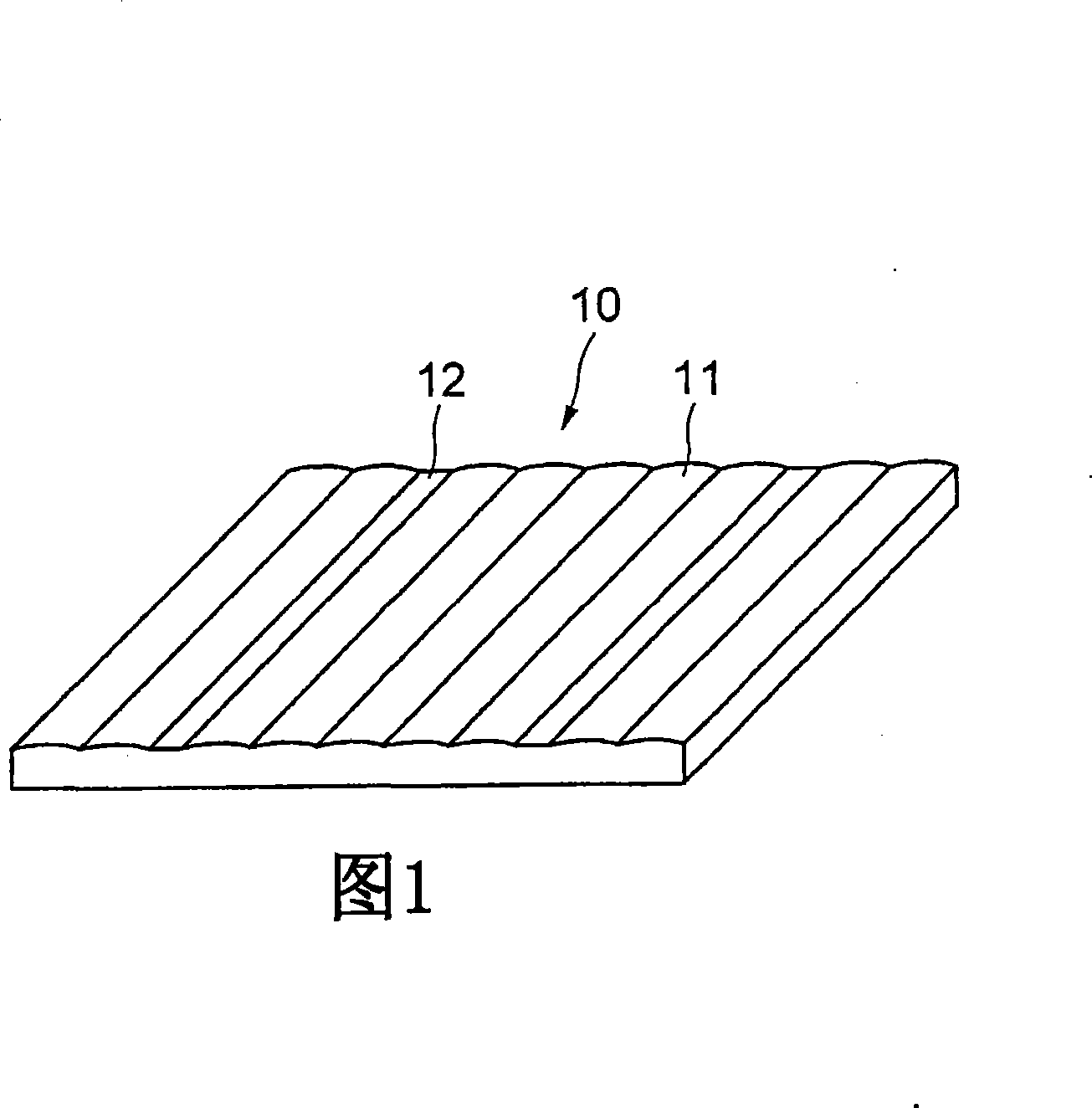
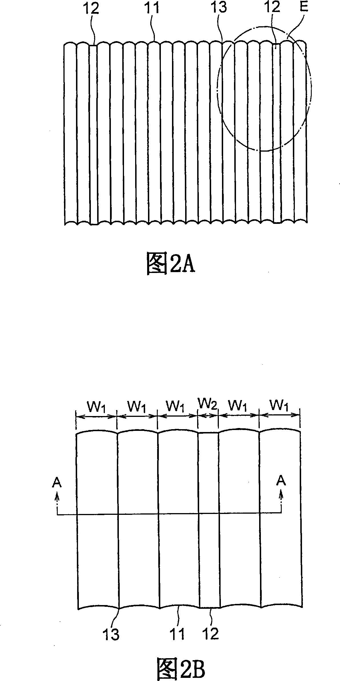
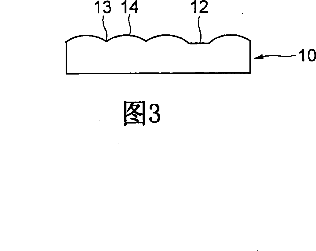
[0066] 1 is a perspective view of a structural form of a lenticular lens sheet according to a first exemplary embodiment of the present invention; FIGS. 2A and 2B are top views of a structural form of a lenticular lens sheet of FIG. 1, wherein 2A is a panoramic view, and 2B is included in 2A Partially enlarged view of the area of ​​E at the end of the lens sheet of the non-periodic planar portion; and FIG. 3 is a cross-sectional view along the line A-A of FIG. 2B.

[0067] In the following exemplary embodiments, a lenticular lens sheet and a fly-eye lens sheet are described as examples, but not limited thereto, and an optical element array including a prism sheet formed with a predetermined pattern, a reflection sheet, and a diffusion sheet can be widely used .

[0068] The lenticular lens sheet 10 according to the f...


PUM


Abstract

The present invention provides an optical element array capable of mounting lenses with low cost and high precision, a display device capable of stereoscopic display using the optical element array, and a method of manufacturing the display device. The lens sheet of the present invention is configured by a plurality of unit lenses and a non-periodic flat portion which functions as a reference mark for positioning. The display device is configured using a lenticular sheet such that the non-periodic planar portion of the lenticular sheet overlaps the alignment marks of the display screen. Since the non-periodic flat portion as the lens reference mark is arranged on the alignment mark, observation shift of the alignment mark due to the lens effect does not occur during the alignment time, and high-precision alignment is achieved.

Description

[0001] This application is based on and claims priority from Japanese Patent Application No. 2006-250922 filed September 15, 2006, the disclosure of which is incorporated herein by reference in its entirety. technical field [0002] The present invention relates to an array of optical elements including a lenticular sheet that provides image display to multiple viewing points using lenticular lenses or fly-eye lenses, in order to provide unique displays such as stereoscopic display and viewing angle control; a display device; and manufacturing the display device, The optical element array and the method for molding the optical element array. Background technique [0003] In response to the demand for complex display devices in recent years, a unique display device that combines an array of optical elements such as a lenticular lens, a prism sheet, or a diffusion sheet with a display screen using a photoelectric element such as liquid crystal, and enables realization of a ster...

Claims


Application Information

Patent Timeline
Patent Type & Authority Applications(China)
IPC IPC(8): G02B3/00G02B3/10G02B3/06G02B27/22H04N13/00B29D11/00G02B30/27G02F1/13
CPCG02B3/0056G02B27/2214G02B3/0025G02B3/0031B29D11/00278G02B3/005G02B3/0075G02B30/27
Inventor 重村幸治高梨伸彰
Owner NEC LCD TECH CORP
Learn More