
Device for positioning the trailing edge of sheets

A sheet and edge technology, applied in the direction of positioning objects, transportation and packaging, sending objects, etc., can solve the problem that the role of the guide roller is no longer enough, heavy weight, etc., to achieve the effect of avoiding the rebound of the sheet

Active Publication Date: 2008-03-19
HEIDELBERGER DRUCKMASCHINEN AG
View PDF3 Cites 2 Cited by
  • Summary
  • Abstract
  • Description
  • Claims
  • Application Information

AI Technical Summary

Problems solved by technology

But at high speeds and heavy grams, the action of the guide rollers alone is no longer sufficient

Method used


Image

  • Device for positioning the trailing edge of sheets
  • Device for positioning the trailing edge of sheets
  • Device for positioning the trailing edge of sheets

Examples


Embodiment Construction

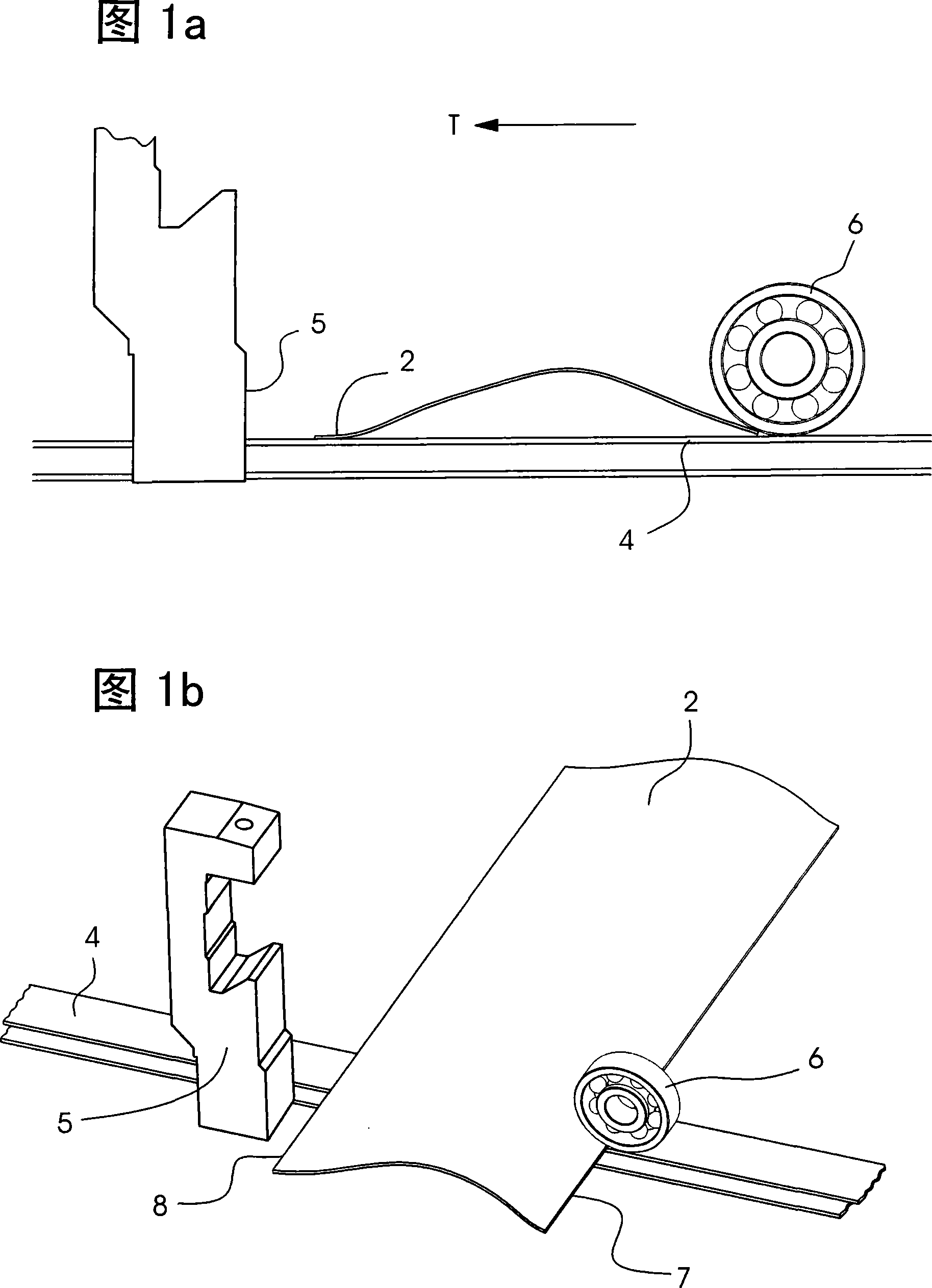
[0027] The principle structure of a device according to the background art is shown in FIGS. 1 a and 1 b.

[0028] The rollers 6 push the sheets 2 together with the conveyor belt 4 against the stop 5 . The sheet 2 stop deforms like a spring and then releases the stored energy as a spring force against the conveying direction. The wedge formed between the roller 6 and the belt 4 is intended to brake the sheet.

[0029] The rollers 6 used today for improved sheet transport and without marking are very flexible and have a very low mass. These advantages during sheet transport are disadvantages during sheet braking. The spring-backed sheet 2 bulges and jacks up the roller 6 . Since the rollers 6 have almost no rolling resistance and no mass, the direction of rotation is now reversed. Sheet 2 is braked only by rolling friction. The strong pressing force of the rollers 6 to prevent the lifting often causes marks on the sheet 2 . These traces are not desired and should be avoid...


PUM


Abstract

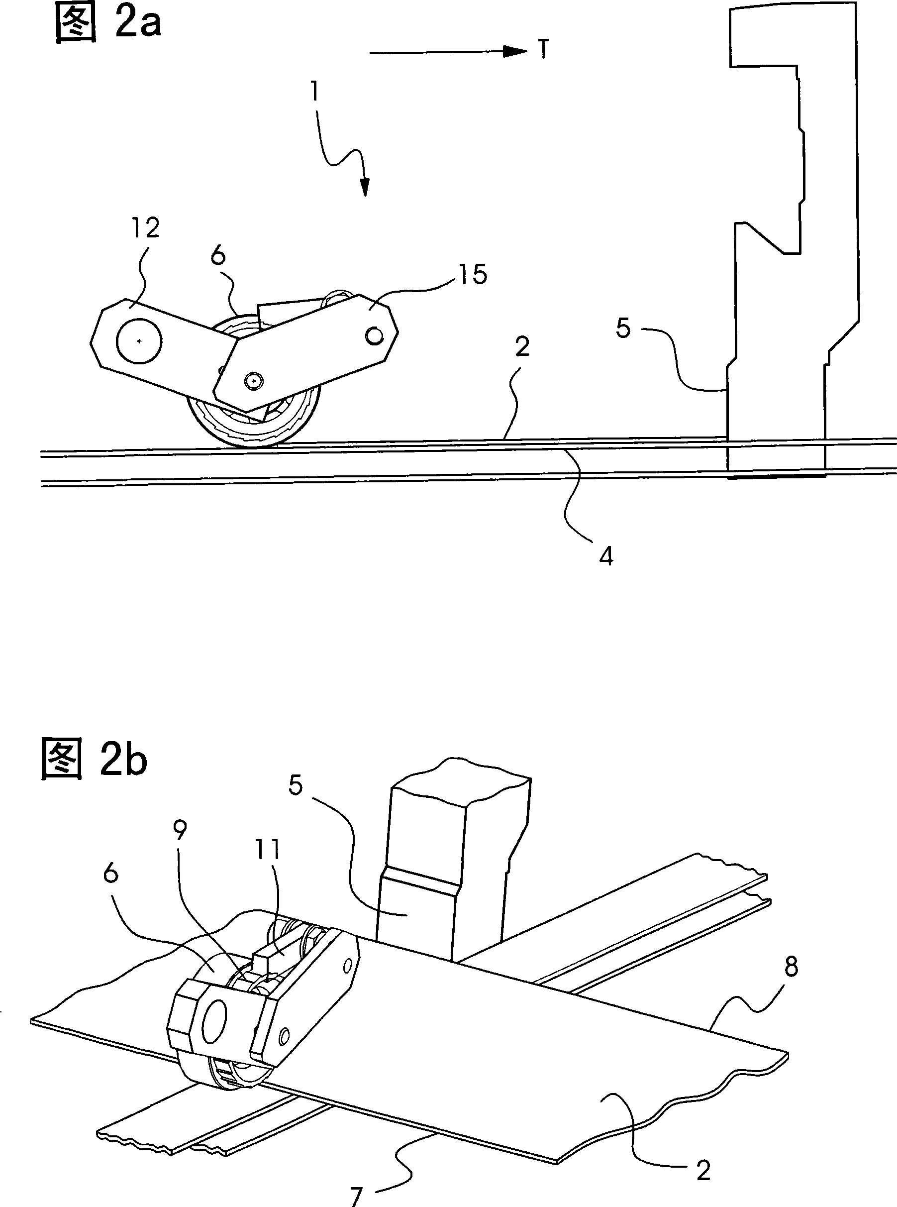
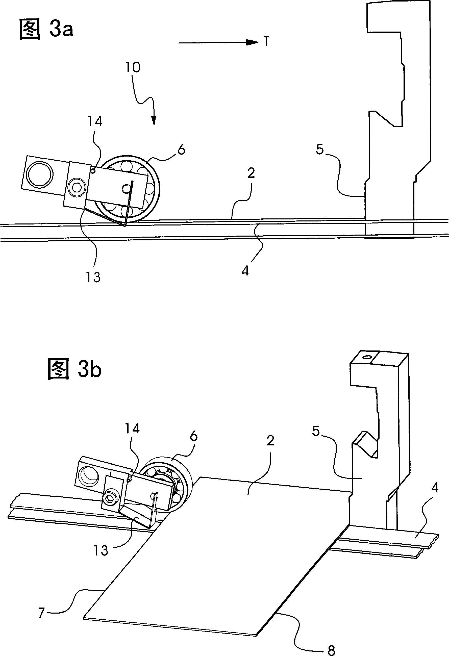
The invention relates to a device for positioning the trailing edge of sheets moving in a mixed style folding machine. The said device is composed pf a conveyor belt where a sheet is conveyed in the conveyor belt against a catch, and at least one roller presses the sheet against the conveyor belt and is adjustable on a rear edge of the sheet, when a front edge of the sheet lies against the catch. The roller is provided with a return stop that prevents reversion of rotation of the roller.

Description

technical field [0001] The invention relates to a device for positioning the rear edge of a sheet-like object which is preferably moved in a hybrid folding machine. Background technique [0002] In mixed grid-knife folders, ie hybrid folders, the parallel creases are folded on the grid-folding principle in the first folding station, while the subsequent cross-creases are made with vertically working folding knives. For this purpose, the folded sheets are transported, after the parallel folding process, to a cross-folding station without slipping by means of a conveyor belt. In order to ensure a truly slip-free conveying, the conveyed flat goods must be restrained and pressed vertically against the conveyor belt. In order to generate the vertical contact force required for this, not only load bearing balls but guide rollers are used. Such a loaded ball system is known, for example, from German utility model DE 84 06 391 . Recently, however, the use of guide rollers as desc...

Claims


Application Information

Patent Timeline
IPC IPC(8): B65H45/12
CPCB65H9/106B65H2701/1313B65H2404/1532B65H29/16B65H45/18
Inventor H·克里斯托夫K-P·施赖伯R·米勒
Owner HEIDELBERGER DRUCKMASCHINEN AG
Learn More