Inverse thermal acoustic imaging part inspection

A part and part feature technology, applied in the field of reverse thermoacoustic imaging parts inspection, can solve the problems of inconspicuous parts failure and difficult detection of small cracks

Inactive Publication Date: 2008-03-12
UNITED TECH CORP
View PDF0 Cites 4 Cited by
  • Summary
  • Abstract
  • Description
  • Claims
  • Application Information

AI Technical Summary

Problems solved by technology

Some part defects such as small cracks are difficult to detect
Also, failures inside a part may not be apparent using traditional non-destructive inspection techniques such as ultrasound, x-ray, fluorescent penetrants, or eddy current

Method used


Image

  • Inverse thermal acoustic imaging part inspection
  • Inverse thermal acoustic imaging part inspection

Examples


Embodiment Construction

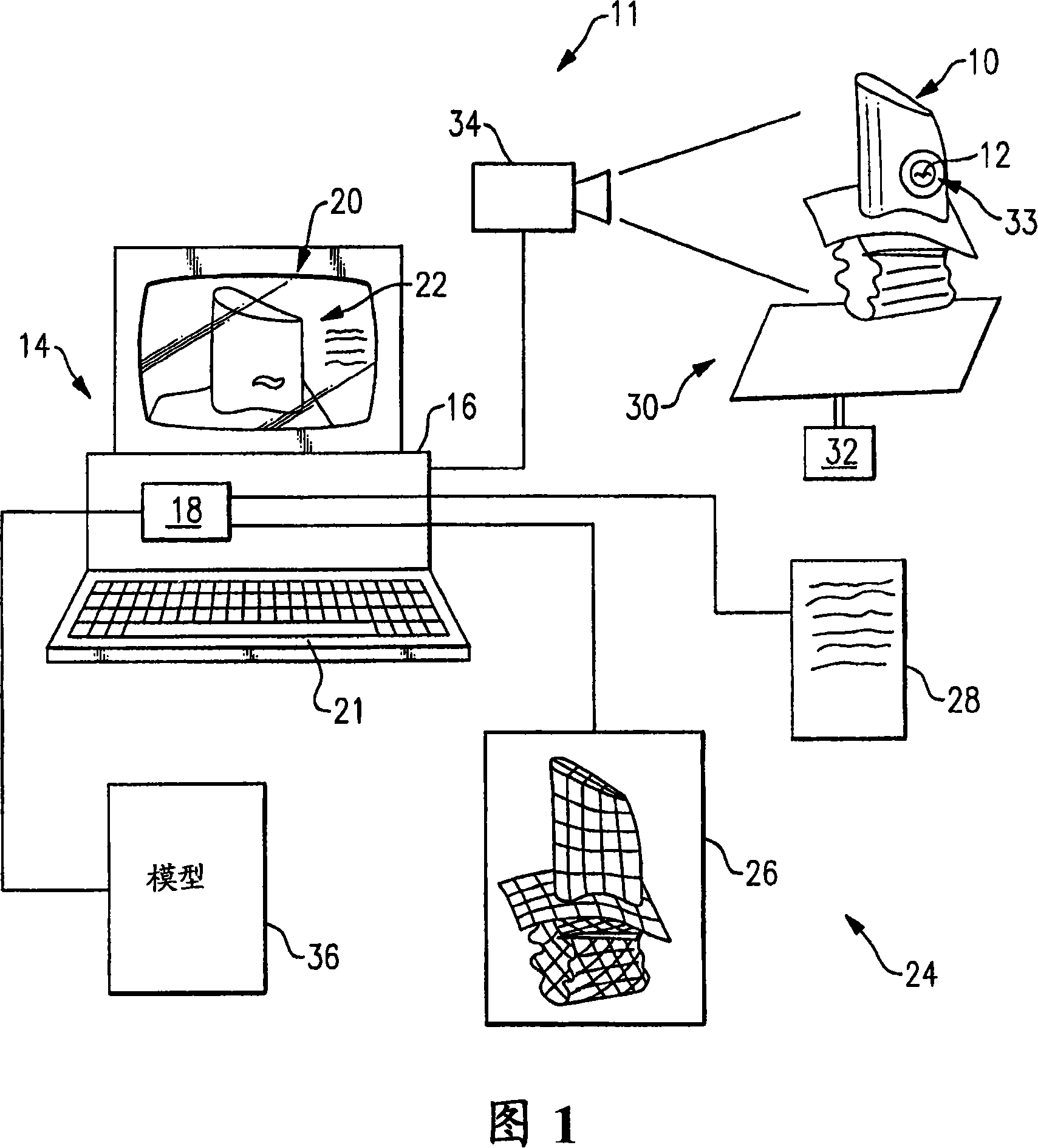
[0009] An inspection system 11 for identifying characteristics, such as defects, in a part 10 is shown in FIG. 1 . The inspection system 11 can be fully automated. The part 10 with the defect 12 is mounted on a vibration device 30 which is excited using a plurality of actuators 32 at different frequencies. The vibrating device 30 may be a shaking table or an ultrasonic device capable of vibrating the part 10 in the range of, for example, 500 Hz-100 kHz.

[0010] Due to the vibrations exerted on the part 10 by the vibrating means 30, heat is generated at any defect or crack in the part 10 due to friction and plastic deformation during each loading cycle. This heating, shown schematically at 33 , causes a temperature rise above the nominal structural temperature of the part 10 . The temperature rise caused by the crack is distributed over a wider range than the strain distortion, and thus can be detected using the infrared camera 34, for example. Images of the exterior of par...


PUM


Abstract

A method of identifying a flaw in a part is provided that includes vibrating a part to induce heat. The heat originates in any flaws in the part. A thermal image is obtained using, for example, an infrared camera. A mathematical representation of the thermophysics, such as the heat conduction or thermal energy equations using the boundary element method or finite element method is used to identify a source and an intensity of the heat identified with the thermal image. Using the source and intensity of the heat, flaw characteristics for the part can be determined. The method is employed using an inspection system (11) that includes a vibration device (30) for vibrating the part (10). An imaging device (34), such as an infrared camera, measures temperature on the surface of the part. An assumption is made or additional measurements are taken to obtain values for surface flux or surface heat transfer coefficients. A processor (16) communicates with the imaging device (34) for receiving the surface temperature. The processor includes computer memory (18) having part characteristics (24) and mathematical equations (36). The processor uses the measured surface temperature, assumed or measured heat flux or heat transfer coefficients, part characteristics and mathematical equations to determine the flaw characteristics in the part.

Description

technical field [0001] The present invention relates to a method and apparatus for inspecting parts, for example to identify defects in the parts. Background technique [0002] Many components must be inspected to ensure that there are no part failures that would affect their use. This is especially true in the case of aircraft components such as turbine wings. Parts must be inspected in a non-destructive manner so that the part can still be used after inspection. Some part defects such as small cracks are difficult to detect. Furthermore, failures within a part may not be apparent using traditional non-destructive inspection techniques such as ultrasound, X-ray, fluorescent penetrants, or eddy current. [0003] What is needed is a non-destructive inspection method and apparatus that can identify part defects such as cracks. Contents of the invention [0004] Provided is a method of identifying defects in a part, including vibrating the part to induce heat. Heat origi...

Claims


Application Information

Patent Timeline
Patent Type & Authority Applications(China)
IPC IPC(8): G01N33/00G01N25/72
CPCG01N25/72
Inventor A·斯塔洛塞尔斯基T·J·马丁C·V·赛维尔Z·欧阳K·D·史密斯
Owner UNITED TECH CORP
Why Eureka
Try Eureka