Twisting head rotor
A rotor and pivot pin technology, applied in textiles, papermaking, yarn, etc., can solve the problems of reducing the cost of removing and installing roll frames, and achieve the effects of preventing insufficient lubricant, reducing costs, and improving productivity
- Summary
- Abstract
- Description
- Claims
- Application Information
AI Technical Summary
Problems solved by technology
Method used
Image
Examples
Embodiment Construction
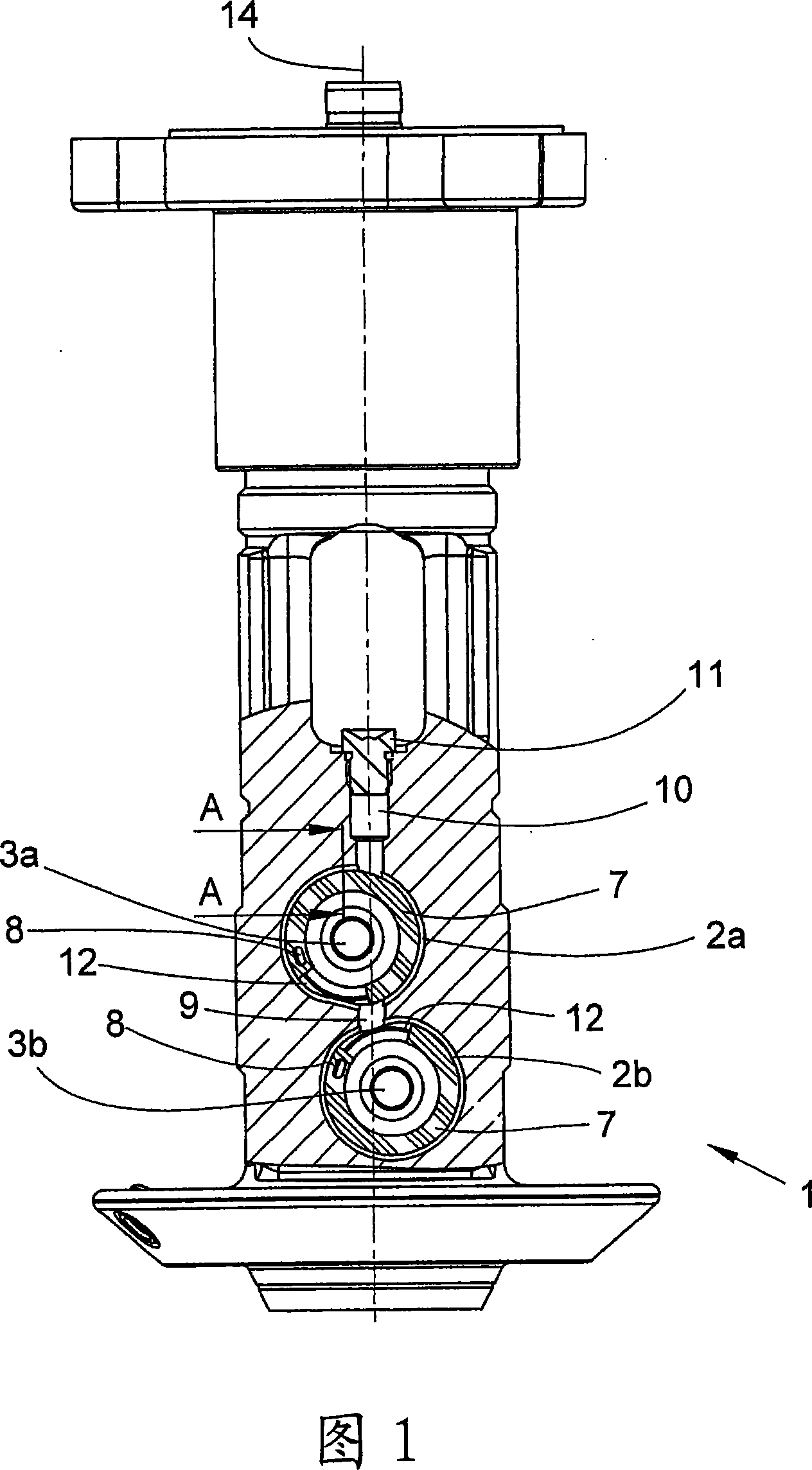
[0023] FIG. 1 shows a twist-head rotor 1 as described in DE 197 00 222 C1, the disclosure of which forms the content of the present description.
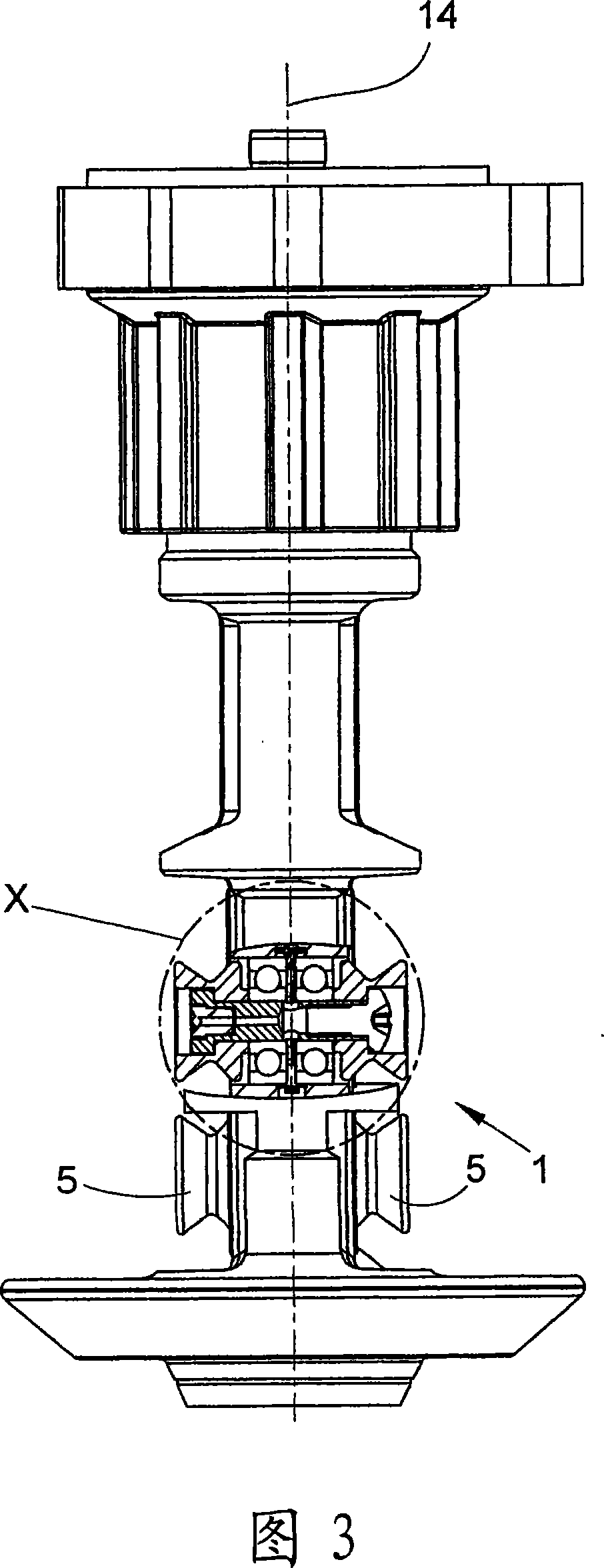
[0024] The twist head rotor 1 is provided with two bearing holes 2 a , 2 b arranged one above the other and perpendicular to the rotation axis 14 of the twist head rotor 1 . The bearing bores 2 a , 2 b are arranged offset rearwardly with respect to the rotation axis 14 of the twist head rotor 1 , respectively. The bearing holes 2a, 2b are intended to receive pivot pins 3a, 3b, respectively, which are mounted by means of two roller bearings 4 in the respective bearing holes 2a, 2b. Two compensating rollers 5 are arranged opposite each other at the ends of the pivot pins 3a, 3b and are separated from each other by the twist head rotor 1 .
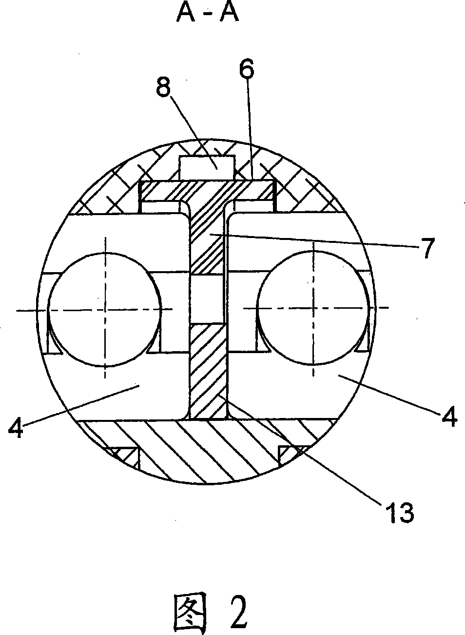
[0025] As shown in FIG. 2, the bearing holes 2a, 2b are divided into two parts for connecting the two roller bearings 4 by means of a peripheral groove 6 coaxial with the longitudinal axis of the ...
PUM
 Abstract
Description
Claims
Application Information
 - Generate Ideas
- Intellectual Property
- Life Sciences
- Materials
- Tech Scout
- Unparalleled Data Quality
- Higher Quality Content
- 60% Fewer Hallucinations
Browse by: Latest US Patents, China's latest patents, Technical Efficacy Thesaurus, Application Domain, Technology Topic, Popular Technical Reports.
© 2025 PatSnap. All rights reserved.Legal|Privacy policy|Modern Slavery Act Transparency Statement|Sitemap|About US| Contact US: help@patsnap.com


