
Image forming apparatus

A technology of imaging equipment and driving force, which is applied in mechanical equipment, equipment of electrical recording technology using charge patterns, electrical recording techniques, etc. The effect of delivering the accuracy guarantee

Active Publication Date: 2008-02-27
KONICA MINOLTA BUSINESS TECH INC
View PDF3 Cites 0 Cited by
  • Summary
  • Abstract
  • Description
  • Claims
  • Application Information

AI Technical Summary

Problems solved by technology

As a result, stress acts on members for holding the input / output shaft and the housing of the imaging device, which raises concerns about deformation
In order to solve this problem, it is necessary to accurately make the shaft eccentricity of the input / output shaft small, and to have a deformation limit in the structure such as the holding part
The structure that allows deformation makes the device itself larger and causes an increase in cost, while the higher precision design makes it difficult to set up / disassemble the imaging unit

Method used


Image

  • Image forming apparatus
  • Image forming apparatus
  • Image forming apparatus

Examples


no. 2 example

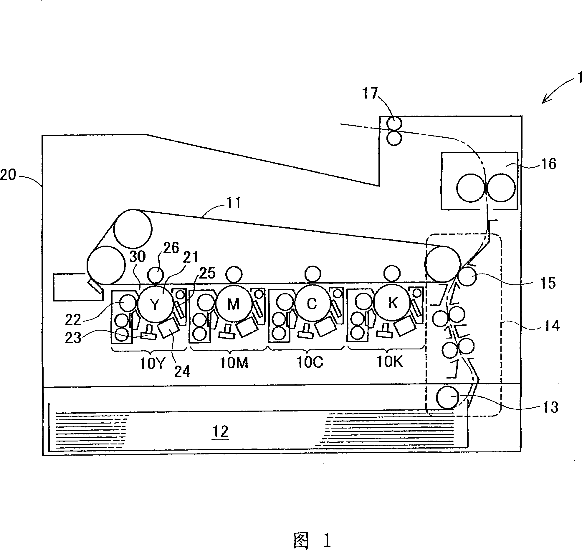
[0081] Hereinafter, a second embodiment of the present invention will be described in detail with reference to the accompanying drawings. This embodiment also relates to a tandem color printer. The overall configuration of this embodiment is the same as that of the first embodiment shown in FIG. 1 .

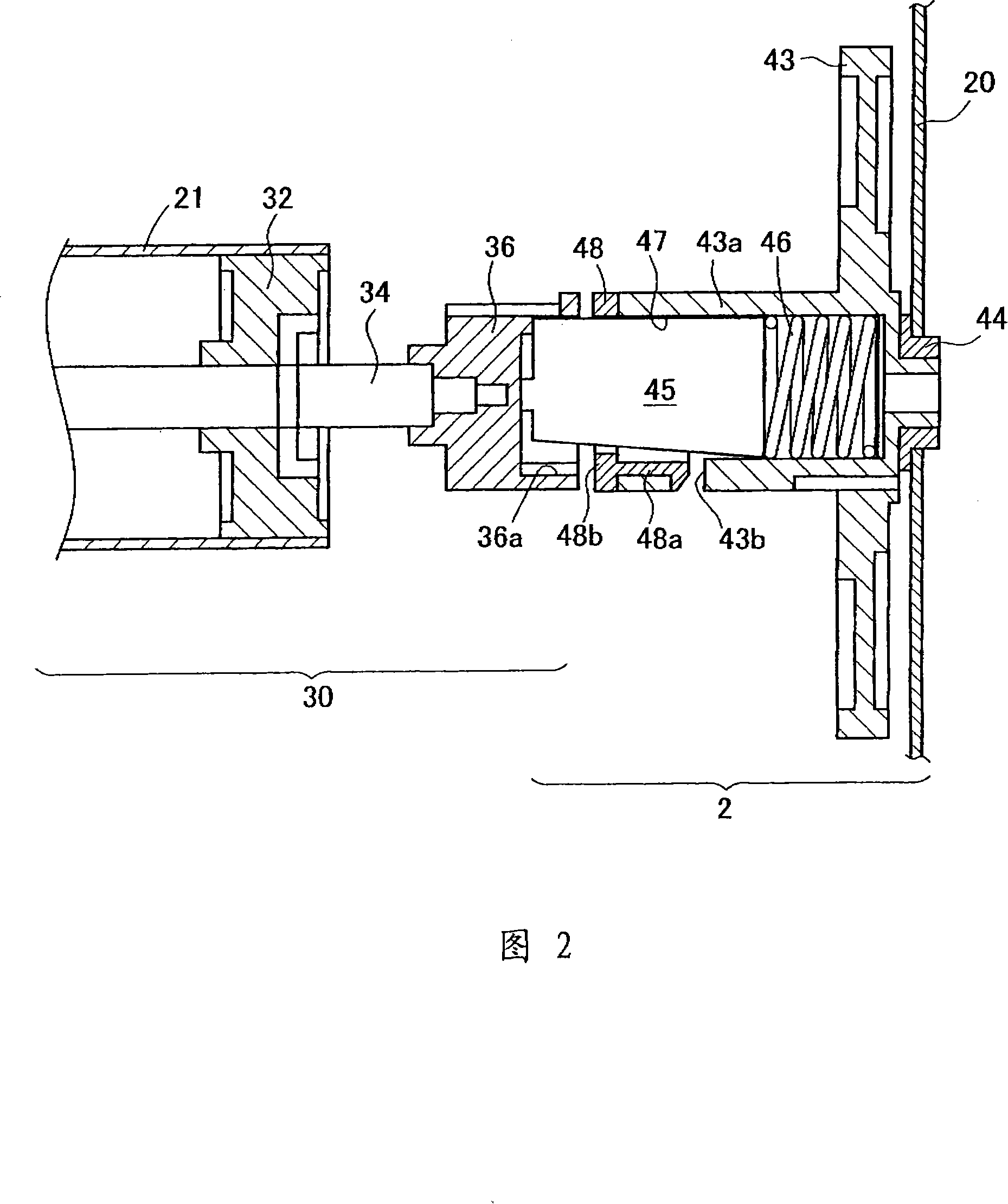
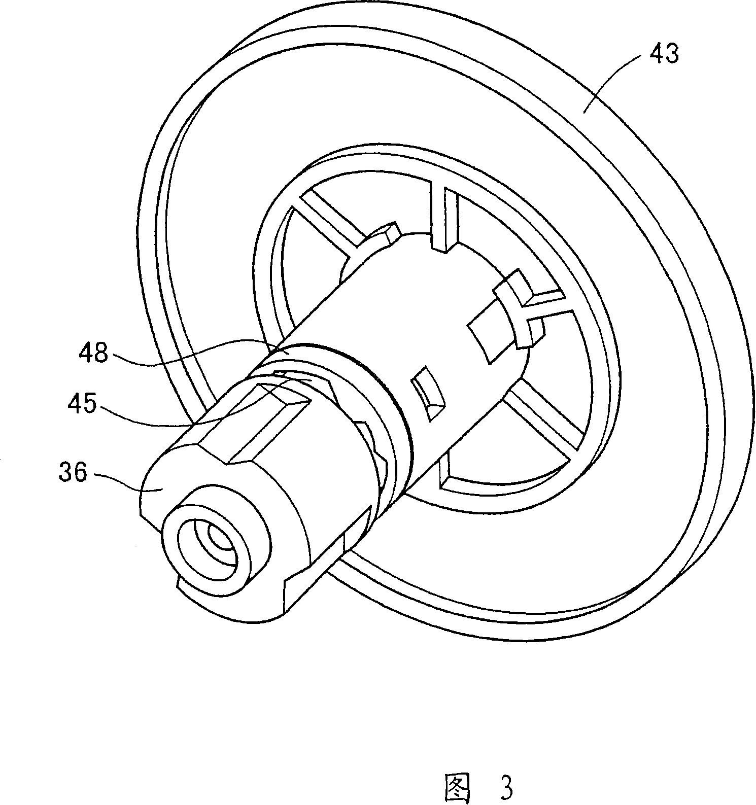
[0082] Next, Figs. 11 and 12 show the outline of the connection part of the main body 2 and the imaging unit 30 of this embodiment. This connecting portion is provided on the deeper side of the color printer in FIG. 1 . Fig. 11 presents a sectional view of the connecting portion. Fig. 12 is an exploded oblique view of the right half of Fig. 11. In the image forming unit 30, as shown on the left side of FIG.

[0083] On the main body 2 side, as shown on the right side of FIG. 11 , a gear 43 is fixed to the housing 20 via a gear shaft support 44 . A link support portion 43a is formed on the gear 43 such that it extends to the left in the figure. The connector supporting porti...

no. 3 example

[0101] Hereinafter, a third embodiment of the present invention will be described in detail with reference to the drawings. This embodiment differs from the first embodiment only in the connection portion between the imaging unit 30 and the main body 2 . Since the entire structure thereof is substantially the same, only differences are described.

[0102] Fig. 17 shows a schematic structure of the connecting portion of this embodiment. In the drawing, the imaging unit 30 is shown on the right. The imaging unit 30 is supported by a housing 31 and includes a photoreceptor 21 , a flange 32 and a shaft support 33 . The flange 32 is fixed to the end of the photoreceptor 21 and rotates integrally with the photoreceptor 21 . The shaft bearing 33 rotatably supports the end of the photoreceptor 21 and is fixed to the casing 31 . A columnar fixing portion 33 a is formed at the left end portion of the shaft support 33 in the figure.

[0103] In the main body 2, as shown on the left ...


PUM


Abstract

The invention provides an image forming apparatus capable of securing rotation transmission accuracy by using simple structure. The image forming apparatus includes: one first driving force transmission component with concave part whose section is multilateral on the position of processing unit, which is used for receiving rotary driving force of the processing unit; one middle driving force transmission component with ladder part whose section is multilateral on the side receiving the rotary driving force of the first driving force transmission component, transmitting the rotary driving force to the processing unit, one end of which locates inside the concave part; one displacement stop part disposed on the concave part, which contacts with the ladder part when the middle driving force component separates from the concave part.

Description

[0001] This application is a divisional application filed on November 30, 2004 with the application number 200410098235.5, the title of the invention is "imaging equipment", and the applicant is Konica Minolta Business Technology Co., Ltd. technical field [0002] The present invention relates to an image forming apparatus, such as a printer, a copier, and the like. More specifically, it relates to an image forming apparatus whose process unit includes a photoreceptor or an intermediate transfer image belt or the like and is detachable. [0003] This application is based on application Nos. 2004-051346 and 2004-137187 in Japan, the contents of which are incorporated herein by reference. Background technique [0004] The wearing member of the image forming apparatus (such as a photosensitive drum, etc.) is generally designed to be a detachable unit so that an end user can replace it with a new one. For example, a tandem type imaging device in which four imaging sections are ...

Claims


Application Information

Patent Timeline
IPC IPC(8): G03G15/00G03G21/00F16D1/02F16D1/06
Inventor 加川哲哉
Owner KONICA MINOLTA BUSINESS TECH INC
Learn More