
Liquid crystal display and driving method thereof

A driving method and technology of liquid crystal display, which can be used in lighting devices, static indicators, sustainable buildings, etc., and can solve problems such as image quality deterioration.

Active Publication Date: 2010-06-09
LG DISPLAY CO LTD
View PDF7 Cites 3 Cited by
  • Summary
  • Abstract
  • Description
  • Claims
  • Application Information

AI Technical Summary

Problems solved by technology

Therefore, even though the response speed of the LCD device is fast, the viewer sees a blurred picture in which the residual image of the previous frame is displayed in the current frame because of the incongruity between the eye movement and the still image of each frame
The phenomenon of motion blur degrades the image quality of images displayed in LCD monitors

Method used


Image

  • Liquid crystal display and driving method thereof
  • Liquid crystal display and driving method thereof
  • Liquid crystal display and driving method thereof

Examples


Embodiment Construction

[0043] Exemplary embodiments of the present invention shown in the drawings will be described in detail below.

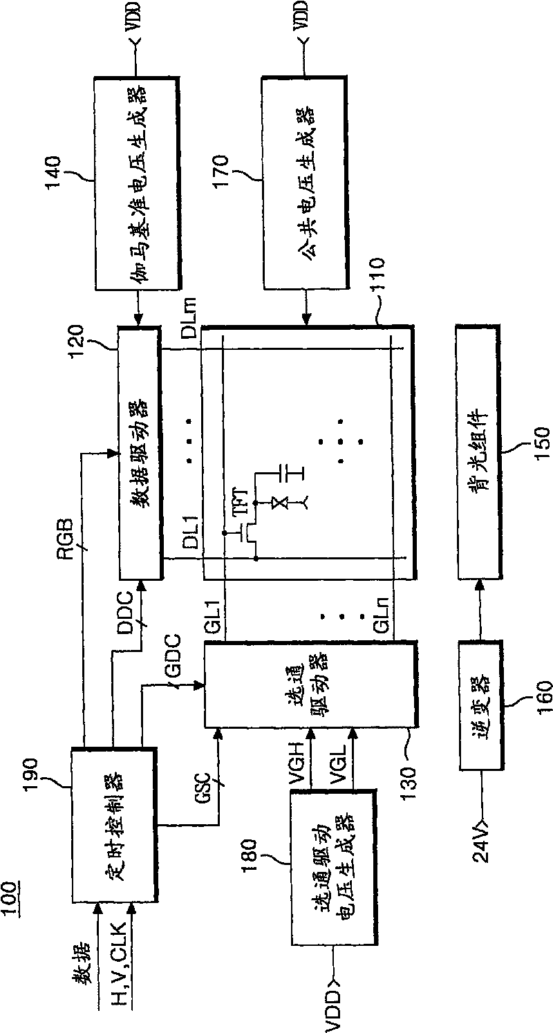
[0044] Figure 5 A schematic diagram of an LCD device according to an embodiment of the present invention is shown. refer to Figure 5 , the LCD device 200 includes a gamma reference voltage generator 140, a common voltage generator 170, and a gate driving voltage generator 180, which have been described with reference to FIG. Figure 5 These components are omitted from .

[0045] Such as Figure 5 As shown, the LCD device 200 includes a data driver 120 , a gate driver 130 and a timing controller 190 similar to the related art LCD device shown in FIG. 2 . Also, the LCD device 200 includes: a backlight assembly 210 for irradiating light to the liquid crystal panel 110; a duty ratio controller 220 for controlling a pulse width modulation (PWM) signal according to an amount of motion of an image displayed on the liquid crystal panel 110. duty cycle, wherein the pulse ...


PUM


Abstract

A liquid crystal display device includes a back light assembly that emits light on a liquid crystal panel; and an inverter that controls brightness of the light emitted from the back light assembly according to a difference between video data of at least three frames that are sequentially inputted to the liquid crystal panel.

Description

technical field [0001] Embodiments of the present invention relate to a liquid crystal display device (LCD device) and a driving method thereof. Background technique [0002] In general, an LCD device controls light transmittance of liquid crystal molecules according to video signals to display images on a liquid crystal panel. A liquid crystal panel includes liquid crystal cells arranged in a matrix. In an active matrix type liquid crystal display, a switching device is provided in each liquid crystal cell. Since an active matrix type LCD device can actively control switching devices in individual cells, it has advantages in displaying moving images. For the switching device of the active matrix liquid crystal display, a thin film transistor (hereinafter referred to as TFT) can be used, as shown in FIG. 1 . [0003] FIG. 1 shows an equivalent circuit diagram of a pixel formed in an LCD device according to the related art. As shown in FIG. 1, in a pixel of an active matr...

Claims


Application Information

Patent Timeline
Patent Type & Authority Patents(China)
IPC IPC(8): G09G3/34G02F1/1362G02F1/133G02F1/13357G09G3/36
CPCG09G2320/103G09G2340/16H05B41/2828Y02B20/186G09G2330/028G09G2320/064G09G2320/106G09G3/342G09G2320/0646G09G2320/0261G09G2310/024Y02B20/00G02F1/133G09G3/36
Inventor 吴东暻
Owner LG DISPLAY CO LTD
Learn More