
Overlapping covering spheroid ablative foci generating system and method

A technology of overlapping coverage and ellipsoids, applied in the field of medical devices, can solve the problems of treatment failure, inability to completely cover tumors, inability to accurately judge complete inactivation, etc., and achieve the effect of reducing damage

Inactive Publication Date: 2008-02-13
BEIJING CANCER HOSPITAL PEKING UNIV CANCER HOSPITAL
View PDF4 Cites 11 Cited by
  • Summary
  • Abstract
  • Description
  • Claims
  • Application Information

AI Technical Summary

Problems solved by technology

[0005] However, most radio frequency devices in the prior art can only produce a spherical coagulation lesion with a diameter of 3 cm to 5 cm in a single needle placement. For larger tumors, a single ablation lesion cannot cover the entire tumor, so multiple needle placements are required. Ablation can completely cover the inactivation, which means that multiple ablation lesions are required to completely cover large tumors
Since tumors are often irregular in shape, and ablation lesions are standard spheres, where to generate ablation lesions and how many ablation lesions can be generated to better cover irregular tumors is a key issue, because if the generated ablation lesions If the number of ablation lesions is not enough, the tumor cannot be completely covered. If the number of ablation lesions is too large, the surrounding healthy tissue will be destroyed. The wrong position of ablation lesions will also lead to poor ablation effect.
It can be seen that the inability of the therapist to accurately judge the number of ablation times (that is, the number of ablation lesions) and the location of the needles (that is, the location of ablation lesions) required to completely inactivate large tumors is an important reason for treatment failure.

Method used


Image

  • Overlapping covering spheroid ablative foci generating system and method
  • Overlapping covering spheroid ablative foci generating system and method
  • Overlapping covering spheroid ablative foci generating system and method

Examples


Embodiment Construction

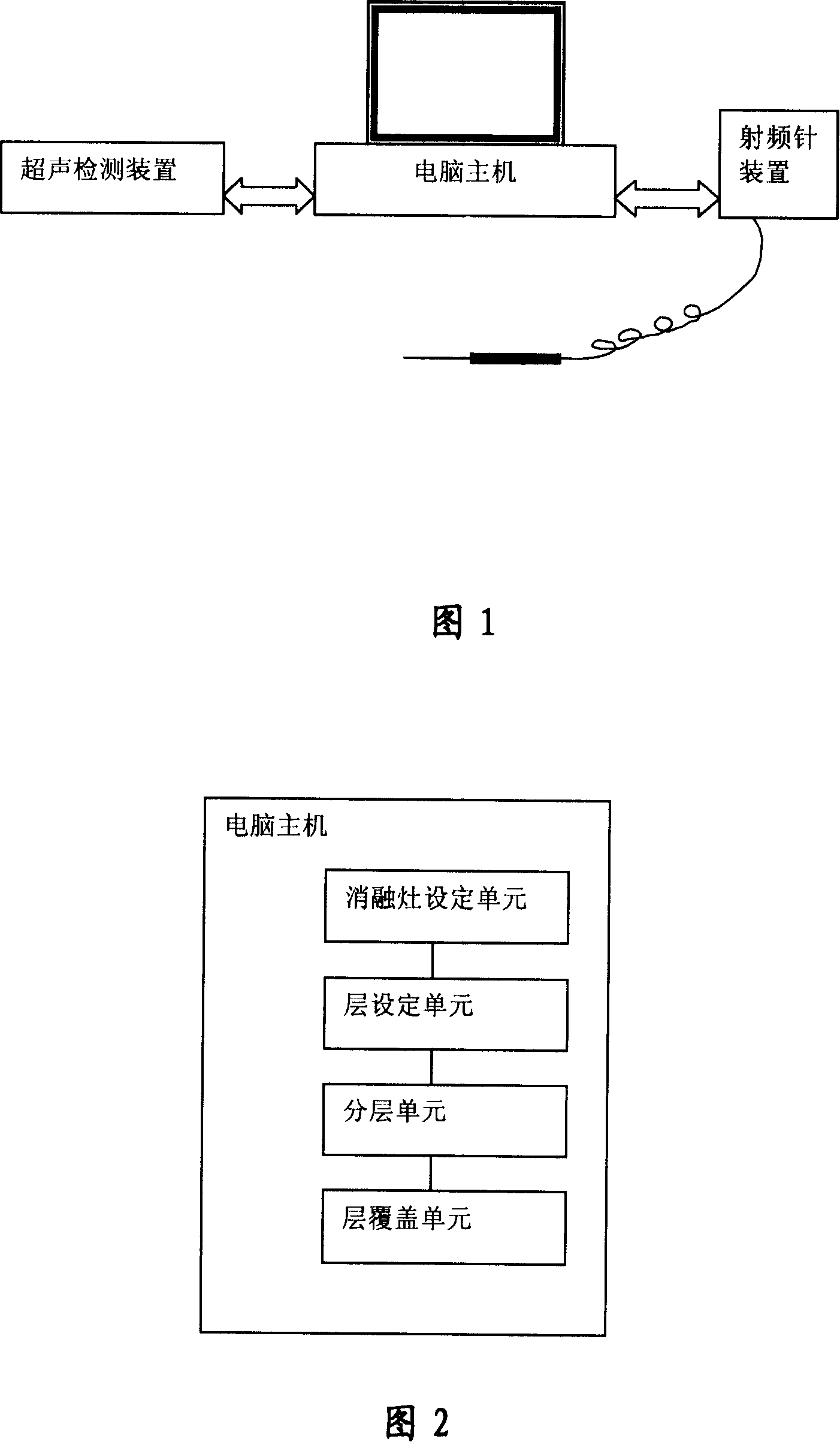
[0024] The specific implementation manner of the present invention will be described below in conjunction with the accompanying drawings. As shown in Figure 1, it is a connection diagram of the system of the present invention, which includes: a computer host, an ultrasonic detection device and a radio frequency needle device; the ultrasonic detection device is used to process the shape of the object to be ablated according to an ellipsoid, Measuring the lengths of the long axis, wide axis and high axis of the ablated object, and inputting the measured data into the computer mainframe;

[0025] As shown in Figure 2, the host computer includes: an ablation lesion setting unit, used to set the size of the ablation lesion generated by the radio frequency needle; a layer setting unit, used to set the area covered by the ablated object The number of layers of ablation lesion required; the layered unit, according to the length of the long axis, wide axis and high axis of the ablated ...


PUM


Abstract

The present invention provides a generating system and method for a overlapping covering the ellipsoid ablation area, which comprises a main engine, a radio frequency needle device and a detection device for the ablation material. The present invention comprises a setting unit for the ablation area, which is used for setting size of the ablation area produced by the radio frequency needle; a layer setting unit, which is used for setting layer number required for covering the ablation material; a layered unit, which divides layers vertical to the high axial according to setting distance relative to center coordinate and the cross section layer equal to layers of the ablation area in the high axial; a layer covering unit, which is used for obtaining numbers of the ablation area demanded by the cross section and the spherical center coordinate of each ablation area relative to the ellipsoid coordinate system; a radio frequency needle device, which is used for generation of the ablation area in corresponding area, according to number of the ablation area sending out by the main engine and the position information. Therefore the largest tumor is covered by the least number of needle application, also damage to the normal tissue around the tumor is reduced.

Description

technical field [0001] The invention relates to the technical field of medical devices, in particular to a radio frequency ablation technology for tumors and other tumors, and specifically to a system and method for generating ablation lesions with overlapping covering ellipsoids. Background technique [0002] Radiofrequency ablation is an effective minimally invasive method for the clinical treatment of liver cancer. Radiofrequency ablation is to insert the electrode needle directly into the tumor under the guidance of ultrasound, and push away the inner trocar. There are 9 ultra-thin multipolar needles on the top that surround the tumor like an umbrella; the radiofrequency energy is emitted through the multipolar needle, The thermal energy can be evenly distributed in the tumor, so that the local tumor will generate high temperature and dryness, and finally coagulation necrosis will occur to achieve the purpose of killing the tumor. [0003] In the prior art, instruments ...

Claims


Application Information

Patent Timeline
IPC IPC(8): A61B18/04A61B17/00A61N7/02
Inventor 陈敏华杨薇
Owner BEIJING CANCER HOSPITAL PEKING UNIV CANCER HOSPITAL
Learn More