
Railway vehicle guiding arm elastic connecting device

A technology for elastic connection and railway vehicles, which is applied in the direction of the device for lateral relative movement between the underframe and the bogie, which can solve the problem of reducing the service life of the guide arm and the connecting device, the inability to set the bending stiffness of the two guide arms, Improve vehicle use costs and other issues to achieve the effect of reducing maintenance work, avoiding direct friction, and reducing use costs

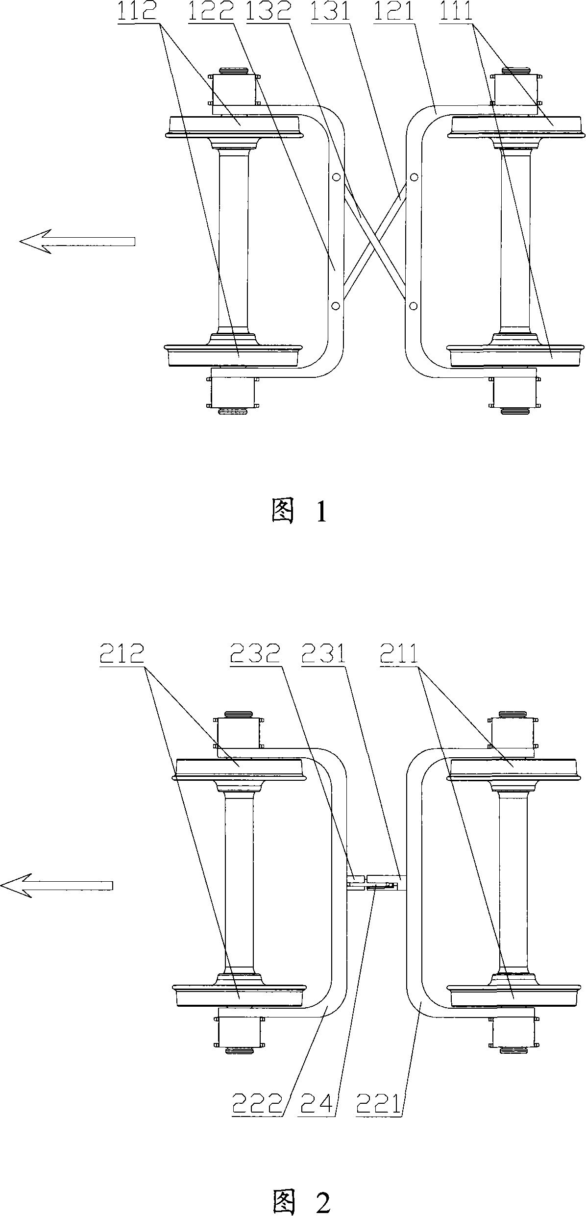
Active Publication Date: 2008-02-06
CRRC QIQIHAR ROLLING CO LTD
View PDF0 Cites 3 Cited by
  • Summary
  • Abstract
  • Description
  • Claims
  • Application Information

AI Technical Summary

Problems solved by technology

During the use of the vehicle, the hinged part of the connecting rod and the guide arm will rotate relative to each other, and this relative rotation will cause greater wear and tear on the hinged part, which will not only reduce the performance of the guide arm, but also cause Increased maintenance work and increased vehicle use costs;
[0007] Secondly, when the railway vehicle brakes, the distance between the guide arms tends to expand, and the above-mentioned connecting device of the prior art fixes the relative position between the guide arms along the longitudinal direction of the railway vehicle (that is, the direction shown by the arrow in Figure 1). , so the guide arm needs to bear a large braking force when the railway vehicle brakes, which will significantly reduce the service life of the guide arm and the connecting device;
[0008] Again, because in the connecting device of the above-mentioned prior art, the two connecting rods are respectively hinged with the two guide arms of the bogie to form a four-bar linkage structure, so it can only improve the shear stiffness between the two guide arms , but the bending stiffness between the two guide arms cannot be set according to actual needs

Method used


Image

  • Railway vehicle guiding arm elastic connecting device
  • Railway vehicle guiding arm elastic connecting device
  • Railway vehicle guiding arm elastic connecting device

Examples


Embodiment Construction

[0033] The core of the present invention is to provide an elastic connection device for connecting the guide arms of the bogies of railway vehicles, which has lower use cost and longer service life, and the bending between the guide arms can be set according to actual needs stiffness.

[0034] In order to enable those skilled in the art to better understand the solution of the present invention, the present invention will be further described in detail below in conjunction with the accompanying drawings and embodiments.

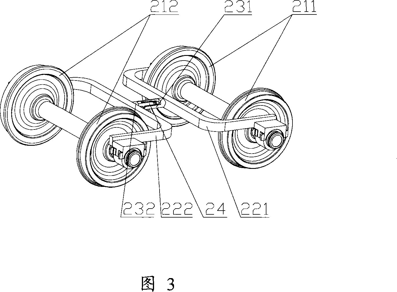
[0035] Please refer to FIG. 2 and FIG. 3 , FIG. 2 is a schematic top view of the elastic connection device and its setting method provided by the embodiment of the present invention, and FIG. 3 is an axonometric schematic view of the elastic connection device and its setting method shown in FIG. 2 .

[0036] A first guide arm 221 and a second guide arm 222 are correspondingly provided between the left and right wheels of the first wheel pair 211 and the secon...


PUM


Abstract

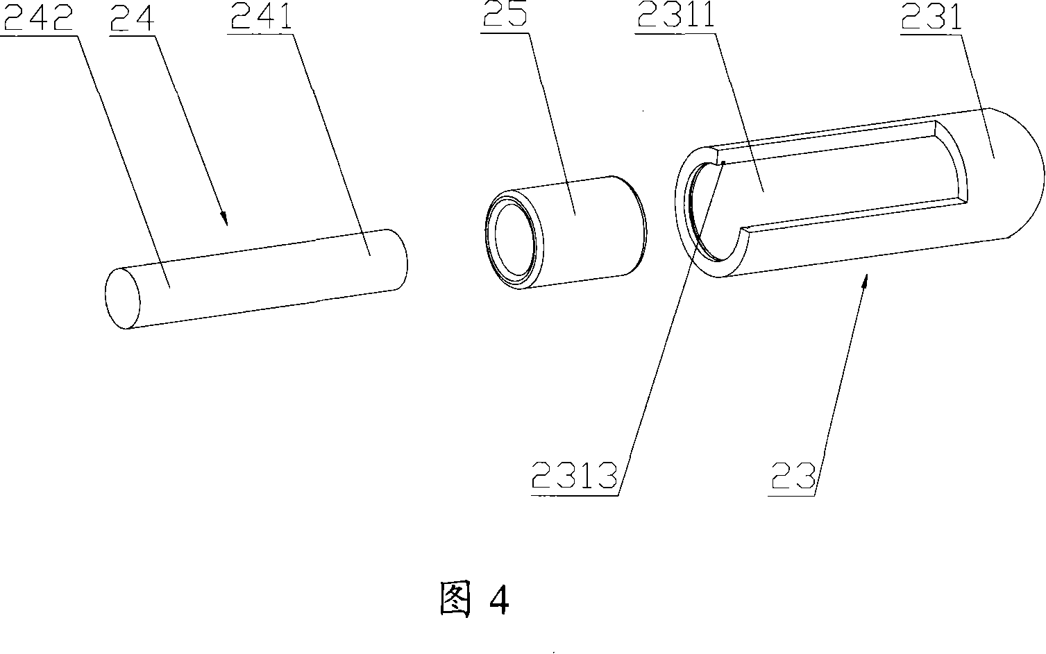
The invention discloses an elastic coupling device for connecting the guide arms of a railway car bogie, which comprises a first connection seat in dead connection with one of guide arms. The first connection seat is provided with a first connection hole which is arranged longitudinally and horizontally along the railway car, and an elastic sleeve is arranged in the connection hole. The elastic coupling device further comprises a connection pin in dead connection with the other guide arm, wherein the expansion end of the connection pin is inserted into the elastic sleeve, and the elastic sleeve has an inner diameter slightly smaller than the diameter of the expansion end of the connection pin and an outer diameter slightly larger than the inner diameter of the first connection hole when the elastic sleeve is in a free state. The elastic coupling device of the invention can not only avoid direct friction between metal structures of the elastic coupling device to reduce abrasion but also ensure that the guide arms do not bear the braking force of the railway car. Additionally, the flexural rigidity between the two guide arms can be adjusted according to actual requirements to meet various actual requirements.

Description

technical field [0001] The invention relates to a connecting device, in particular to a connecting device for elastically connecting a guide arm of a bogie of a railway vehicle. Background technique [0002] As we all know, in order to increase the critical speed of the railway vehicle in meandering and improve the curve passing performance of the railway vehicle, connecting devices are usually arranged between the guide arms (or called sub-frames) of the railway vehicle bogie. [0003] Please refer to FIG. 1 . FIG. 1 is a schematic top view of a connecting device and its arrangement in the prior art. [0004] A first guide arm 121 and a second guide arm 122 are correspondingly provided between the left and right wheels of the first wheel pair 111 and the second wheel pair 112 of the railway vehicle bogie, respectively. As shown in Figure 1, the first guide arm 121 and the second guide arm 122 are both "C"-shaped frames, and their open ends are connected to the bearing sadd...

Claims


Application Information

Patent Timeline
IPC IPC(8): B61F5/24
Inventor 杨爱国胡用生刘振明邢书明
Owner CRRC QIQIHAR ROLLING CO LTD
Learn More