Frequency conversion type intelligent type valve actuator

A valve execution and intelligent technology, applied in the direction of valve details, valve devices, mechanical equipment, etc., can solve the problems of application limitations, motor temperature rise, precision distortion, etc., achieve high-precision position continuous detection, simplify the structure of the actuator, The effect of continuously adjustable running speed

Inactive Publication Date: 2008-01-30
孙力
View PDF0 Cites 16 Cited by
  • Summary
  • Abstract
  • Description
  • Claims
  • Application Information

AI Technical Summary

Problems solved by technology

[0002] At present, the valve actuators widely used all use three-phase AC voltage to directly drive the motor, and drive the valve to run through the mechanical transmission device. The multi-cycle damping oscillation phenomenon occurs during positioning, which greatly reduces the positioning accuracy of the actuator to the valve. In addition, because the starting current of the motor is several times the rated current, the temperature rise of the motor rises sharply, and it cannot operate continuously and frequently for a long time.
In addition, the existing actuators all use three-phase AC motors, and their application is greatly limited for sites that do not have a three-phase AC grid
[0003] On the other hand, most of the valve position detection methods of existing actuators use gear transmission, counter amplification, and then output through potentiometers, cams and contacts. After such a complicated electromechanical process, its accuracy will be greatly distorted. , cannot achieve high-precision measurement. In addition, due to the limitation of the number of mechanical contacts on the cam, the output detection value can only be an intermittent analog signal, which cannot achieve full-stroke high-precision position control.

Method used


Image

  • Frequency conversion type intelligent type valve actuator
  • Frequency conversion type intelligent type valve actuator
  • Frequency conversion type intelligent type valve actuator

Examples


Embodiment Construction

[0025] The present invention will be further described below in conjunction with accompanying drawing and specific embodiment:

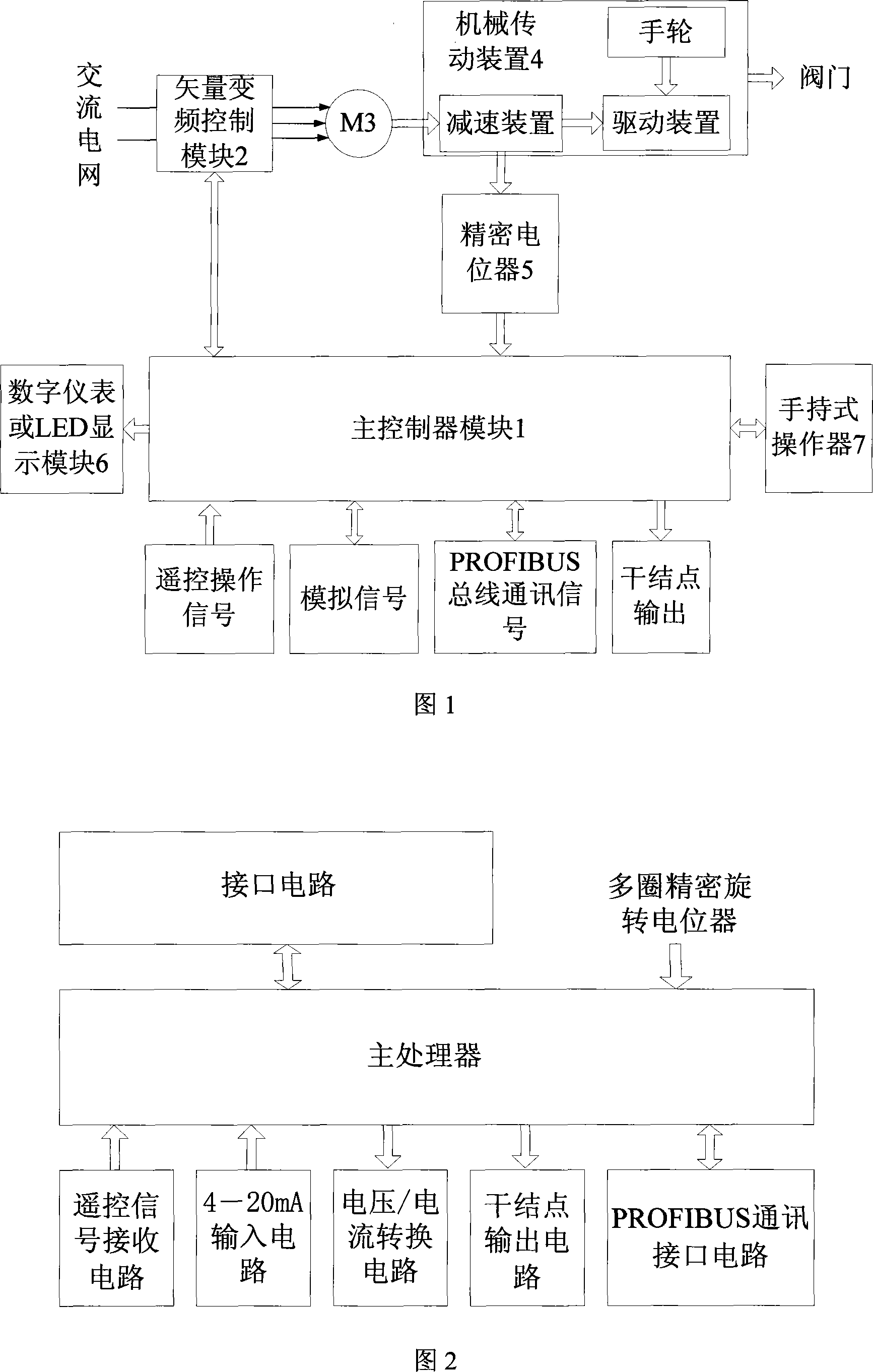
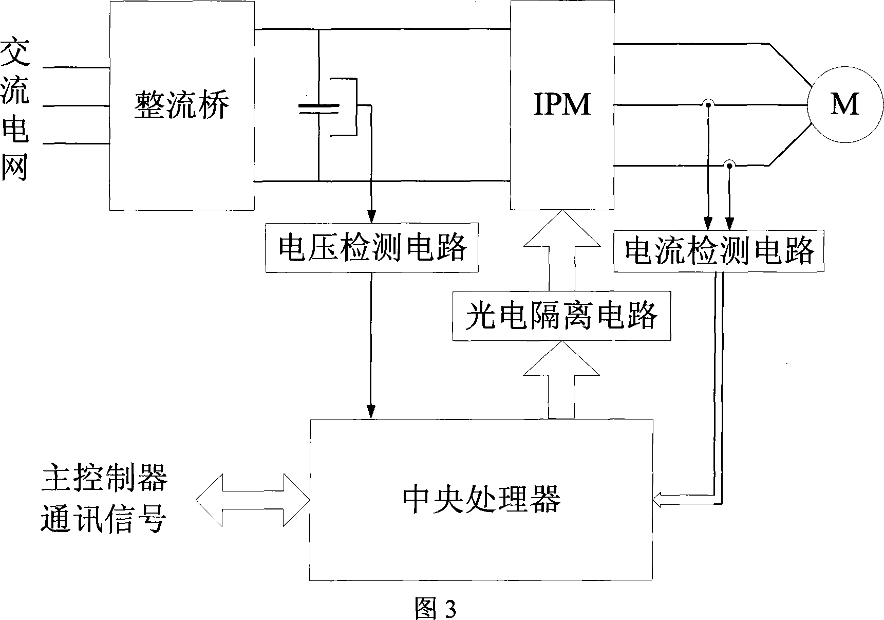
[0026] Referring to Fig. 1, this embodiment includes a main controller module 1, a vector frequency conversion control module 2, an asynchronous motor 3, a mechanical transmission device 4, a multi-turn precision rotary potentiometer 5, a display module 6 and a hand-held operator 7, and the vector frequency conversion control The input end of module 2 is connected to the AC power grid, the output end is connected to the asynchronous motor 3, the shaft end of the asynchronous motor 3 is connected to the mechanical transmission device 4, the output end of the mechanical transmission device 4 is connected to the valve, and the 5th shaft end of the multi-turn precision rotary potentiometer is connected to the mechanical transmission device Device 4 is connected.

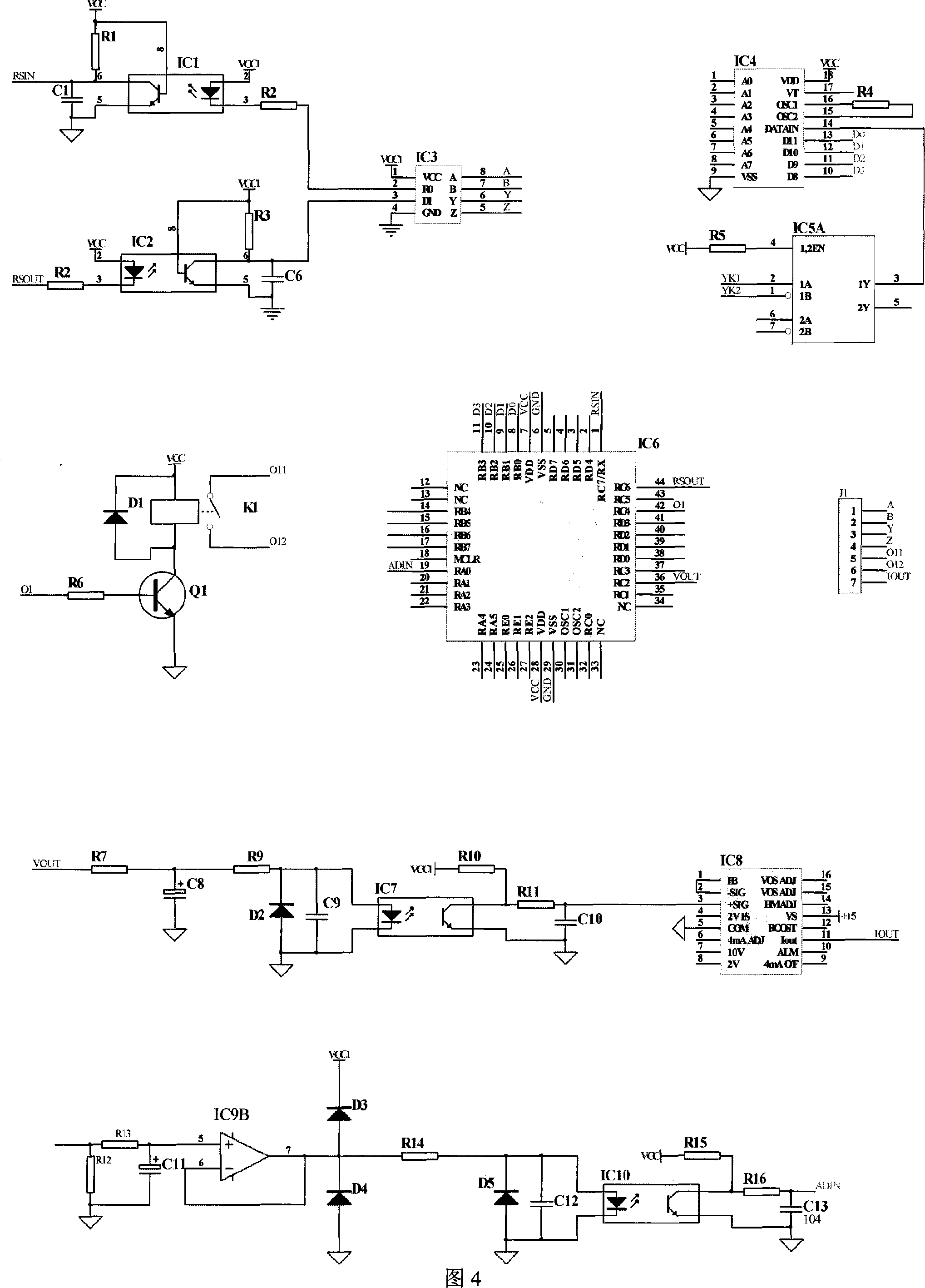
[0027]The vector frequency conversion control module 2 is connected with the main controlle...


PUM


Abstract

The invention relates to frequency conversion intelligent valve executing mechanism, comprising a main controller module 1, a vector frequency conversion control module 2, an asynchronous motor 3, a mechanical transmission device 4, a multi-circle precision rotating potentialmeter 5, a display module 6, and a handy operator 7. The invention is mainly characterized in that: the asynchronous motor is driven by the vector frequency conversion control module, and the precision rotating potentialmeter is used as a position sensor, to control the valve position by adopting whole digital proportional close-loop regulation type, and the control type comprises a plurality of control modes such as local remote control operation, handy operator control, long distance analog control, and bus control, etc, and a low temperature-rise special frequency conversion motor. The invention has the advantages of small size, high reliability, high positioning precision, having servo control characteristics, and easy networked control, etc. Compared with traditional executing mechanism, the invention greatly enhances the positioning precision, can continuously work for a long time, and automatically adapt to the working condition of single phase or three phase DC power.

Description

(1) Technical field [0001] The invention relates to a valve actuator, in particular to a variable frequency intelligent valve actuator. (2) Background technology [0002] At present, the valve actuators widely used all use three-phase AC voltage to directly drive the motor, and drive the valve to run through the mechanical transmission device. The phenomenon of multi-cycle damping oscillation occurs during positioning, which greatly reduces the positioning accuracy of the actuator to the valve. In addition, because the starting current of the motor is several times the rated current, the temperature rise of the motor rises sharply, and it cannot operate continuously and frequently for a long time. In addition, the existing actuators all use three-phase AC motors, and their application is greatly limited for sites that do not have a three-phase AC grid. [0003] On the other hand, most of the valve position detection methods of existing actuators use gear transmission, count...

Claims


Application Information

Patent Timeline
IPC IPC(8): F16K31/04H02P27/06G08C19/00
Inventor 孙力刘大为吴凤江赵克
Owner 孙力
Why Eureka
Try Eureka