
Light emitting diode module group

A technology of light-emitting diodes and modules, applied in electrical components, electrical solid-state devices, circuits, etc., can solve the problems of general products without structure and inconvenience, and achieve the effect of reducing steps and time, assisting heat dissipation, and ensuring light-emitting quality.

Inactive Publication Date: 2008-01-23
GIGNO TECH CO LTD
View PDF0 Cites 5 Cited by
  • Summary
  • Abstract
  • Description
  • Claims
  • Application Information

AI Technical Summary

Problems solved by technology

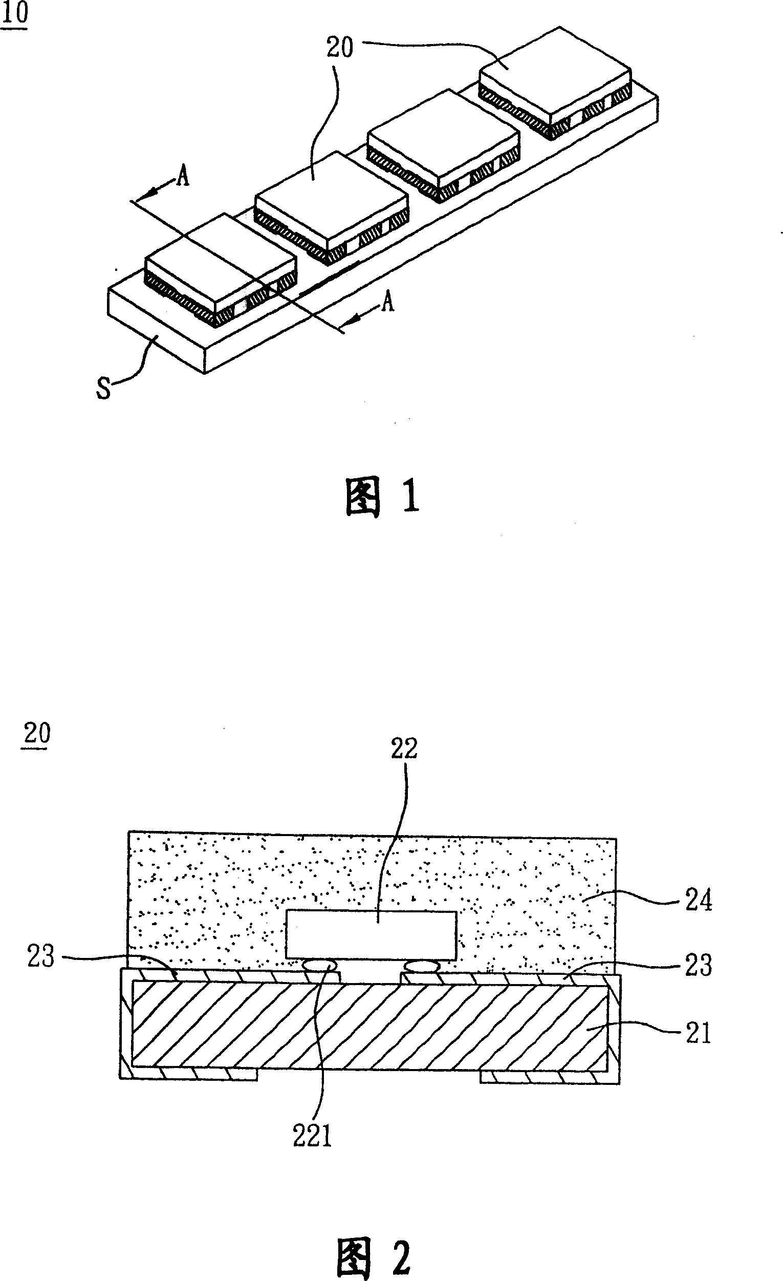
[0010] It can be seen that the above-mentioned existing light-emitting diode modules obviously still have inconveniences and defects in structure and use, and need to be further improved urgently.
In order to solve the above-mentioned problems, the relevant manufacturers have tried their best to find a solution, but no suitable design has been developed for a long time, and the general products do not have a suitable structure to solve the above-mentioned problems. This is obviously related. The problem that the industry is eager to solve

Method used


Image

  • Light emitting diode module group
  • Light emitting diode module group
  • Light emitting diode module group

Examples


Embodiment Construction

[0063] In order to further explain the technical means and effects of the present invention to achieve the intended purpose of the invention, the specific implementation, structure, characteristics and effects of the light-emitting diode module proposed according to the present invention will be described below in conjunction with the accompanying drawings and preferred embodiments. , as detailed below.

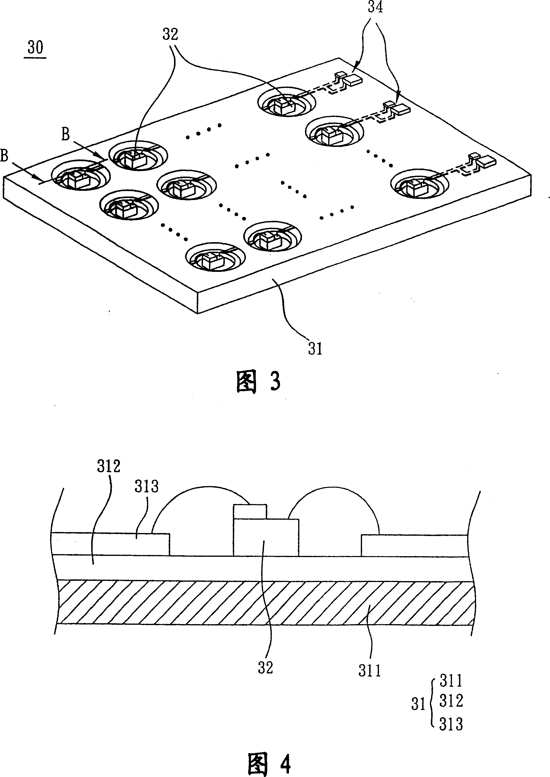
[0064] Please refer to FIG. 3 , the LED module 30 includes a metal circuit substrate 31 and a plurality of LED dies 32 . It should be noted that the number and arrangement of the LED chips 32 in the LED module 30 are not limited. In this embodiment, the light emitting diode dies 32 are arranged in an array as an example, of course, each light emitting diode die 32 may also be arranged in a straight line.

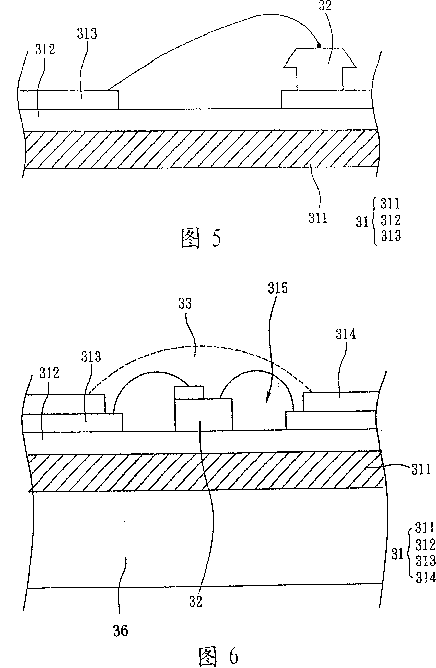
[0065] Please refer to FIG. 3 and FIG. 4 at the same time. FIG. 4 is a schematic cross-sectional view along the line B-B in FIG. The metal circuit substrate 31 sequential...


PUM


Abstract

The present invention relates to a LED module, which comprises a metal circuit substrate, a plurality of LED crystal grains. Wherein, the metal circuit substrate is composed of a metal layer, an insulating and heat conducting layer and a circuit layer. These LED crystal grains are arranged on the metal circuit substrate and electrically connected with the circuit layer.

Description

technical field [0001] The present invention relates to a light emitting module (that is, a module, hereinafter referred to as a module), in particular to a light emitting diode module (LIGHT EMITTING DIODE MODULE). Background technique [0002] A light-emitting diode is a light-emitting element made of semiconductor materials. It has two electrode terminals. When a voltage is applied between the terminals and a very small voltage is passed through, the remaining energy can be converted into light through the combination of electron holes. The form of stimulated release. [0003] Different from ordinary incandescent light bulbs, light-emitting diodes are cold-emitting, which have the advantages of low power consumption, long life of components, no need for warm-up time, and fast response. Coupled with its small size, vibration resistance, suitable for mass production, it is easy to make extremely small or array light-emitting modules according to application requirements, s...

Claims


Application Information

Patent Timeline
Patent Type & Authority Applications(China)
IPC IPC(8): H01L25/00H01L25/075H01L23/36H01L23/488
CPCH01L2924/0002H01L2224/49107H01L2224/48091H01L2224/48465H01L2224/16225H01L2224/73265
Inventor 林峰立
Owner GIGNO TECH CO LTD
Learn More