
Fuser roller, fusing unit, image-forming apparatus, and method thereof

A technology for fixing rollers and images, applied in the field of fixing rollers, image forming devices with the fixing unit, and fixing units, which can solve the problems of shortening the life of pressing rollers and peeling off of elastic layers, etc.

Inactive Publication Date: 2008-01-16
SAMSUNG ELECTRONICS CO LTD
View PDF1 Cites 8 Cited by
  • Summary
  • Abstract
  • Description
  • Claims
  • Application Information

AI Technical Summary

Problems solved by technology

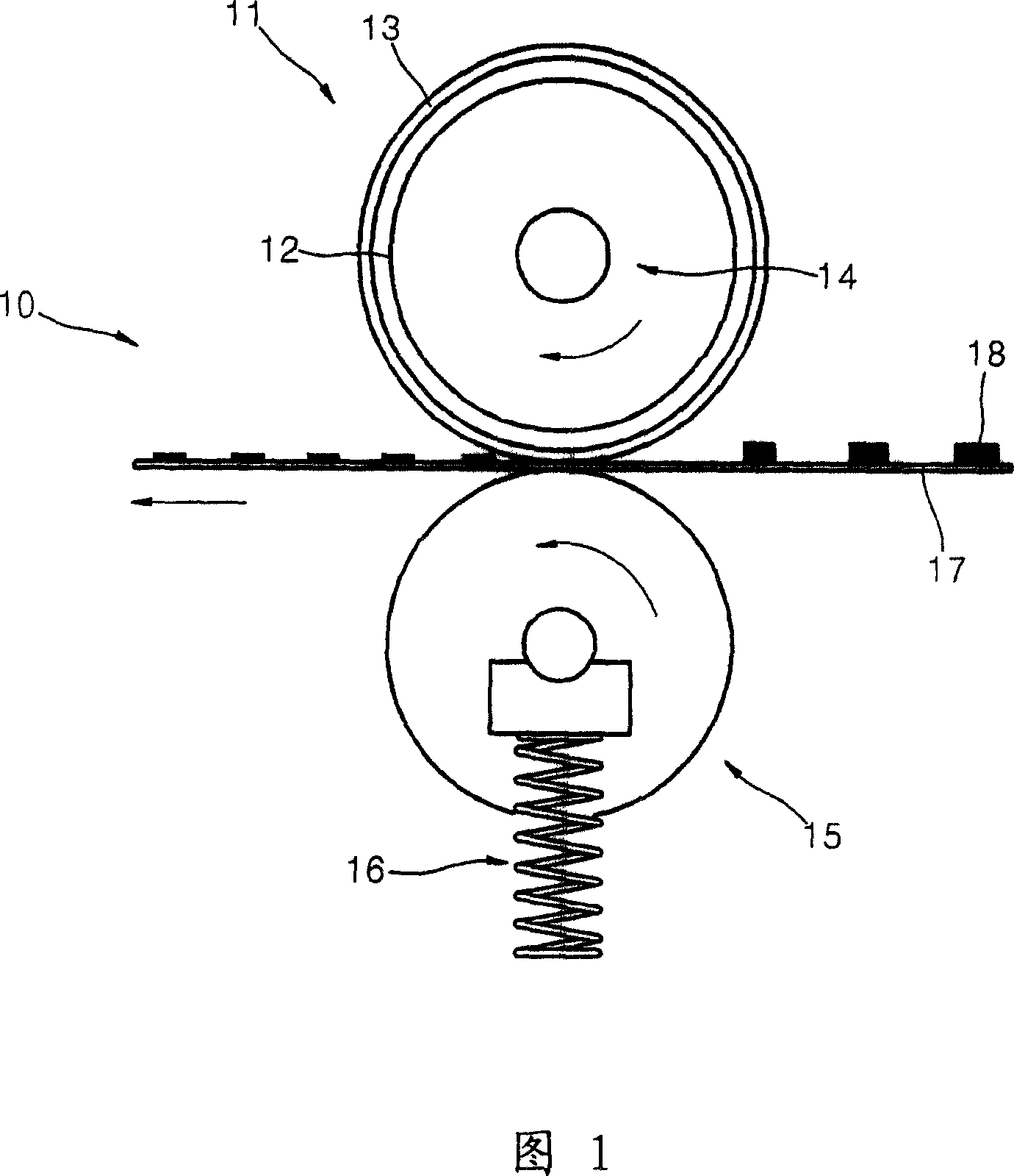
[0011] However, when a low-hardness elastic layer is used, heat radiated from the heating portion and pressure from the pressing roller stress the elastic layer and shorten the life of the pressing roller, and peeling between the fixing portion 12 and the elastic layer occurs, with the result that the elastic layer fall off

Method used


Image

  • Fuser roller, fusing unit, image-forming apparatus, and method thereof
  • Fuser roller, fusing unit, image-forming apparatus, and method thereof
  • Fuser roller, fusing unit, image-forming apparatus, and method thereof

Examples


Embodiment Construction

[0039] Reference will now be made in detail to embodiments of the present general inventive concept, examples of which are illustrated in the accompanying drawings, wherein like reference numerals refer to like elements throughout. The embodiments are described below in order to explain the present general inventive concept by referring to the figures.

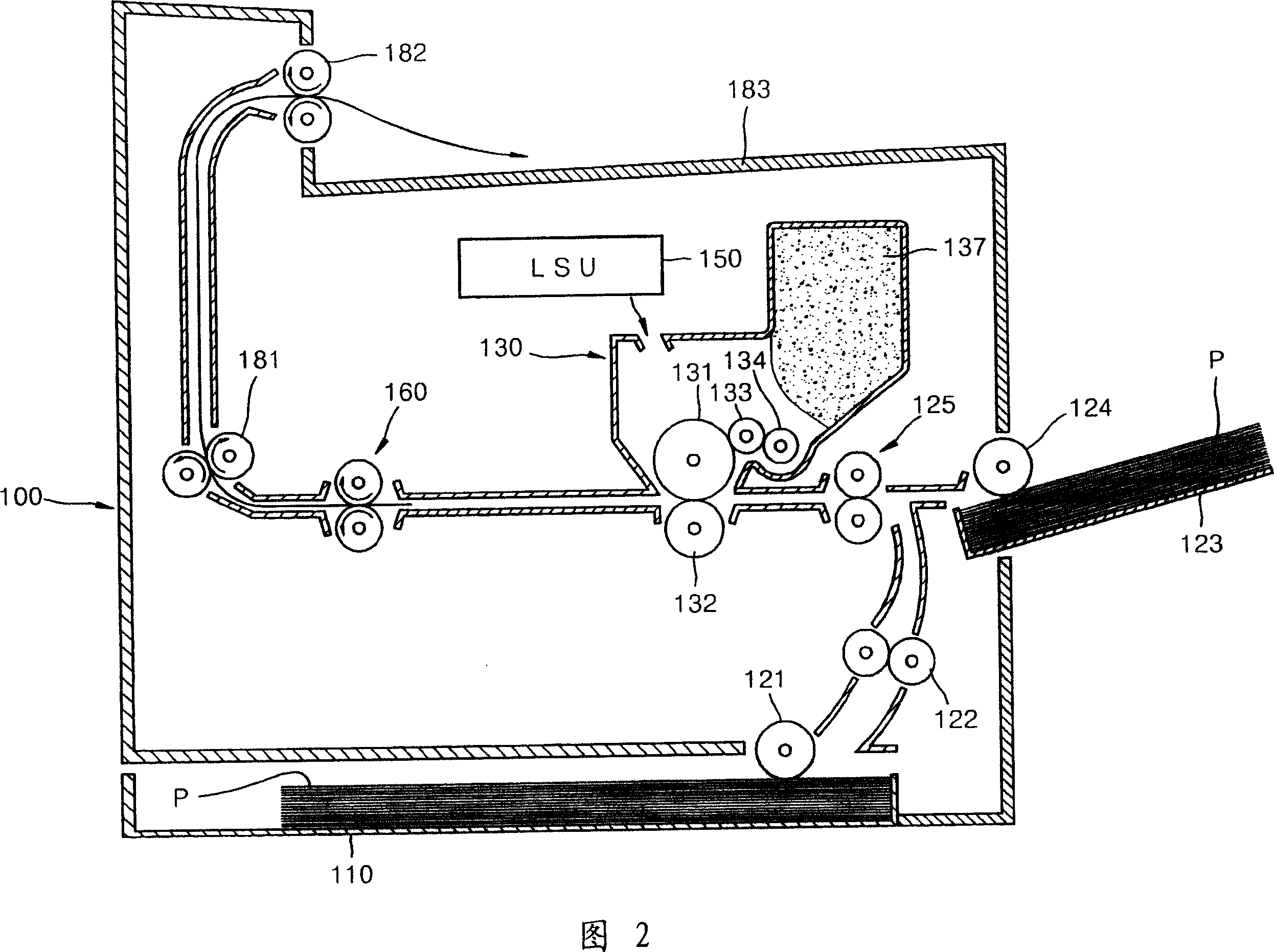
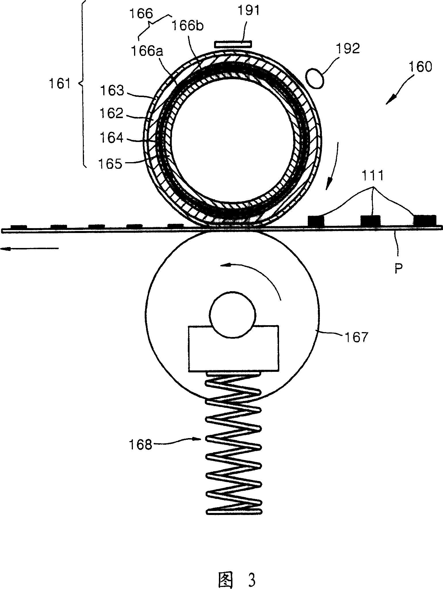
[0040] 2 is a schematic vertical sectional view showing an example configuration of an image forming apparatus having a fixing unit; FIG. 3 is a vertical sectional view showing a fixing unit of the image forming apparatus; FIG. Structure; FIG. 5 is an enlarged cross-sectional view showing the A region in FIG. 4 according to an embodiment of the general inventive concept; FIG. 6 is an enlarged cross-sectional view showing the A region in FIG. 4 according to another embodiment of the general inventive concept Area A.

[0041] Referring to FIGS. 2 to 4 , a cassette 110 for loading printing media (P) is removably installed at the...


PUM


Abstract

A fuser roller (161) and a fusing unit (160) including the fuser roller (161) are to be used in an image-forming apparatus. The fuser roller (161) includes a tubular fusing portion (162), an inner tube (165), and a heating portion (164). The inner tube (165) is inserted into the fusing portion (162). The heating portion (164) is installed to enclose an outer surface of the inner tube (165) and press against an inner surface of the fusing portion (162), and to radiate heat. The fusing portion (162) is surface treated to have a roughness factor of Ra 3 - 5[mu]m.

Description

technical field [0001] The present general inventive concept relates to a fuser roller, a fusing unit, and an image forming apparatus having the same, and more particularly, to an image forming apparatus having a fuser roller by Applying heat and pressure thereto fixes the toner to the print medium to form an image. Background technique [0002] An electrophotographic image forming apparatus first forms an image to be printed as an electrostatic latent image on a photosensitive medium, then uses toner to develop the electrostatic latent image, transfers the developed toner image to a printing medium, and fixes the toner image onto the print media. [0003] FIG. 1 is a vertical sectional view showing an exemplary configuration of a conventional fixing unit of an image forming apparatus. [0004] Referring to FIG. 1 , the fixing unit 10 includes a fixing roller 11 and a pressing roller 15 . [0005] The fixing roller 11 includes a tubular fixing portion 12 and a heating por...

Claims


Application Information

Patent Timeline
Patent Type & Authority Applications(China)
IPC IPC(8): G03G15/20G03G15/00
CPCG03G15/2053G03G15/2057G03G2215/2048
Inventor 李承埈金欢谦薛东辰
Owner SAMSUNG ELECTRONICS CO LTD
Learn More